Working Principle of Universal Coupling
A universal coupling, also widely known as a universal joint, is a fundamental mechanical transmission component designed to solve the core problem of power transmission between two non-collinear rotating shafts. Unlike rigid couplings that only work efficiently when connected shafts maintain perfect coaxial alignment, this flexible mechanical structure enables stable torque and rotational speed transmission under conditions of angular misalignment, axial offset, and slight radial displacement between the driving shaft and driven shaft. Its unique spatial motion compensation capability makes it indispensable in various mechanical transmission systems, ranging from traditional industrial machinery and transportation equipment to modern automated mechanical devices. The entire working logic of the universal coupling is built on spatial linkage kinematics and mechanical force transmission principles, realizing flexible and continuous power output through the coordinated motion of its core components.
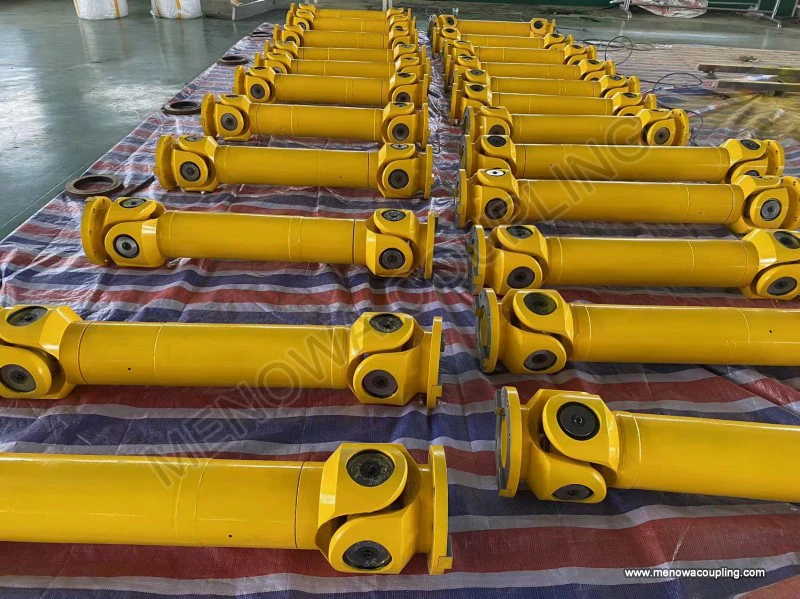
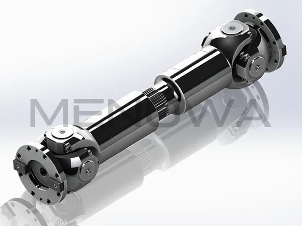
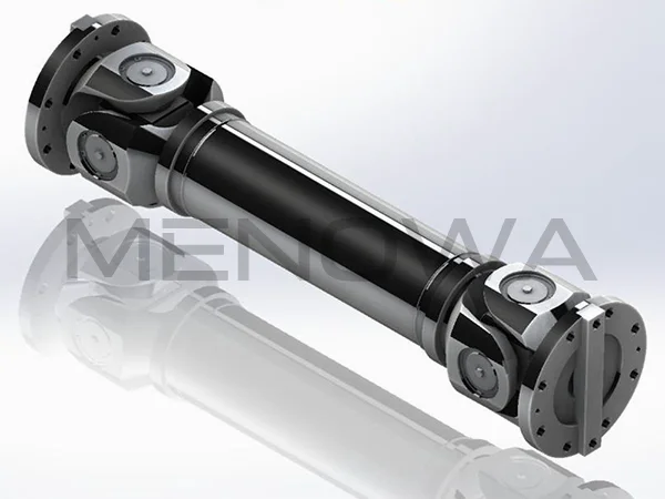
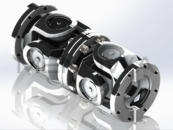
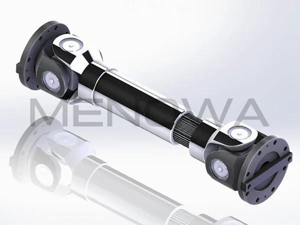
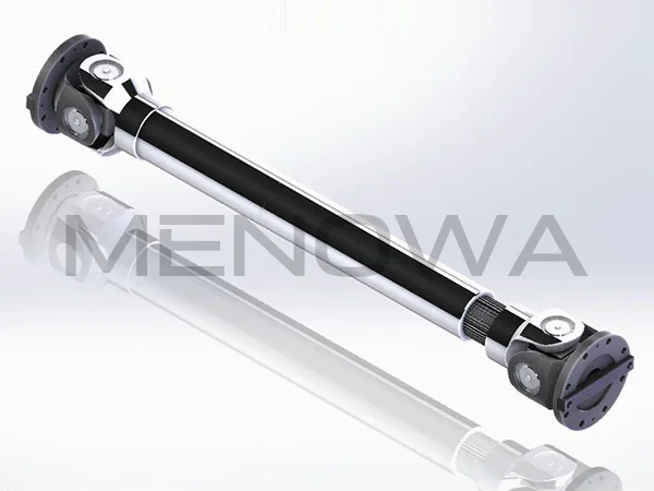
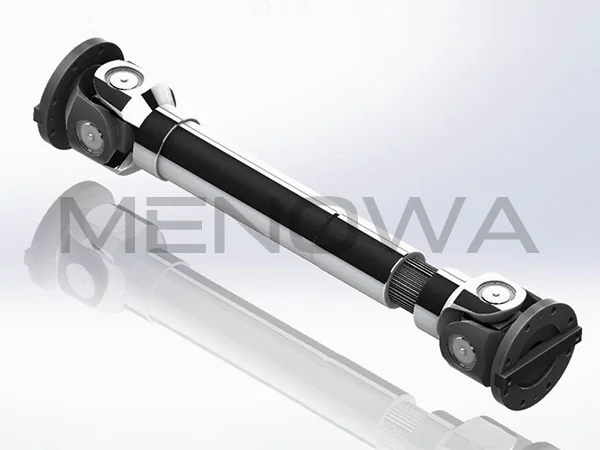
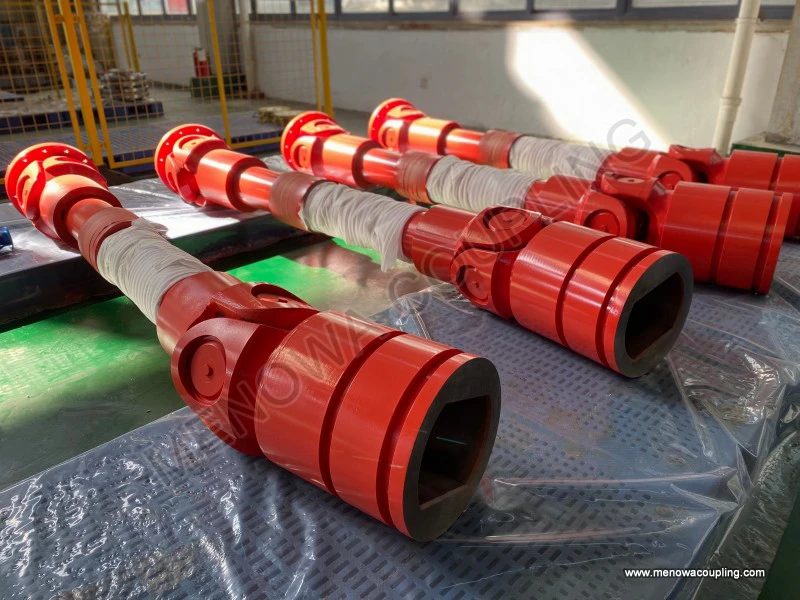
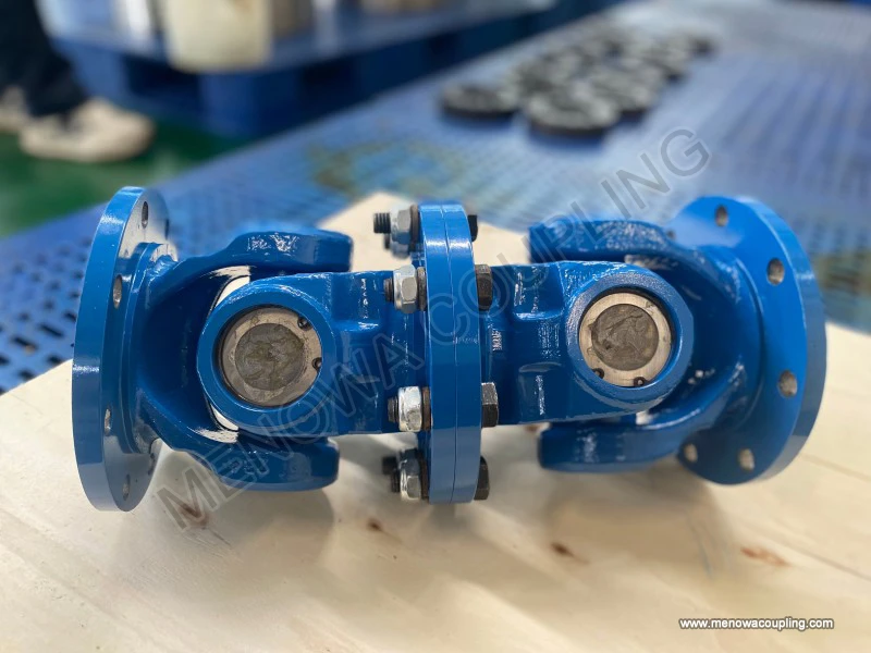
The basic structural composition lays the foundation for its functional principles, and every core component undertakes irreplaceable motion and force transmission tasks. The standard universal coupling structure mainly consists of two shaft yokes and a central cross-shaped spider, together with auxiliary rotating connecting parts. The two yokes are respectively fixed to the end parts of the driving shaft and the driven shaft, forming the input and output ends of the transmission system. The cross-shaped spider, as the core connecting and force-transmitting component, has four mutually perpendicular shaft necks, each installed inside the mounting hole of the yoke through precision rotating auxiliary structures. This assembly method forms a mutually perpendicular hinged connection between the two yokes, allowing free spatial swinging and rotational adaptation between the input end and output end. The ingeniousness of this structure lies in its two-degree-of-freedom motion characteristic: the cross spider can not only rotate synchronously with the driving shaft around the main shaft axis but also swing freely within a certain angular range relative to the yokes, which fundamentally breaks the transmission limitation of rigid structures that rely on fixed coaxial rotation.
The basic power transmission process of a single universal coupling runs through continuous cyclic mechanical motion. When the power system drives the driving shaft to perform constant-speed circular rotation, the driving yoke fixed on the shaft rotates synchronously with it. The rotational torque and motion of the driving yoke are transmitted to the cross spider through the connecting rotating parts, driving the cross spider to follow the driving shaft for circular revolution. During this process, the cross spider continuously adjusts its spatial attitude in real time according to the angular offset between the two shafts. The four shaft necks of the cross spider transmit the received rotational force to the driven yoke stably, and the driven yoke then drives the connected driven shaft to complete rotational motion, thereby realizing the whole process of power transmission from the input shaft to the output shaft. In the ideal state where the driving shaft and driven shaft maintain complete coaxial alignment without any angular deviation, the universal coupling operates in a stable constant-speed transmission state, and the rotational speed of the driven shaft remains completely consistent with that of the driving shaft throughout the rotation cycle, with no motion fluctuation or torque loss.
The most typical working characteristic of a single universal coupling is the inherent non-constant-speed transmission effect under angular misalignment conditions, which is the core mechanical property that must be mastered in its working principle. When there is a certain included angle between the axis of the driving shaft and the driven shaft, even if the driving shaft maintains absolutely uniform circular rotation, the instantaneous angular velocity of the driven shaft will produce periodic alternating changes within one rotation cycle. This velocity fluctuation originates from the spatial geometric motion relationship of the cross spider and yokes. In the rotation cycle, when the plane of the driving yoke is parallel to the offset plane of the two shaft axes, the rotational arm of the driving force acting on the cross spider reaches the maximum value, and the driven shaft obtains the maximum instantaneous angular velocity; when the driving yoke rotates to be perpendicular to the offset plane of the shaft axes, the force transmission arm shrinks to the minimum state, and the instantaneous angular velocity of the driven shaft drops to the lowest point. This periodic speed change repeats twice in every full rotation of the shaft, forming a regular speed fluctuation law.
The amplitude of the driven shaft’s velocity fluctuation is directly positively correlated with the misalignment angle between the two shafts. The smaller the angular offset, the weaker the speed variation and the more stable the transmission process; the larger the offset angle, the more intense the instantaneous speed fluctuation, and the more obvious the resulting periodic acceleration and deceleration motion. This non-constant-speed characteristic will inevitably produce additional alternating mechanical load on the transmission system during operation, including periodic torque impact, vibration and mechanical shear force. Long-term operation under such alternating loads will cause wear of connecting components, increased system vibration and noise, and even affect the running accuracy and service life of the entire mechanical equipment. Therefore, a single universal coupling is usually not suitable for independent use in high-precision, high-speed and stable transmission scenarios, and is mostly applied in low-speed, low-precision or intermittent working conditions.
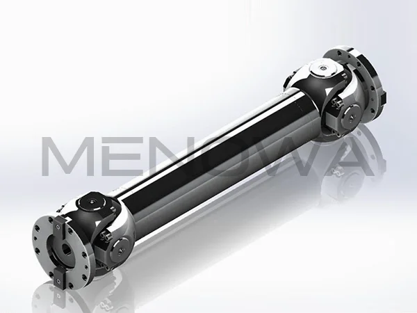
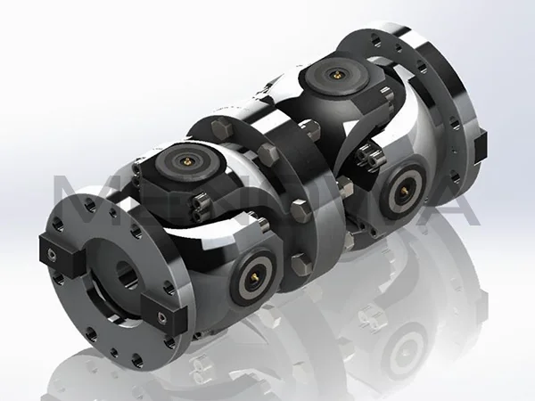
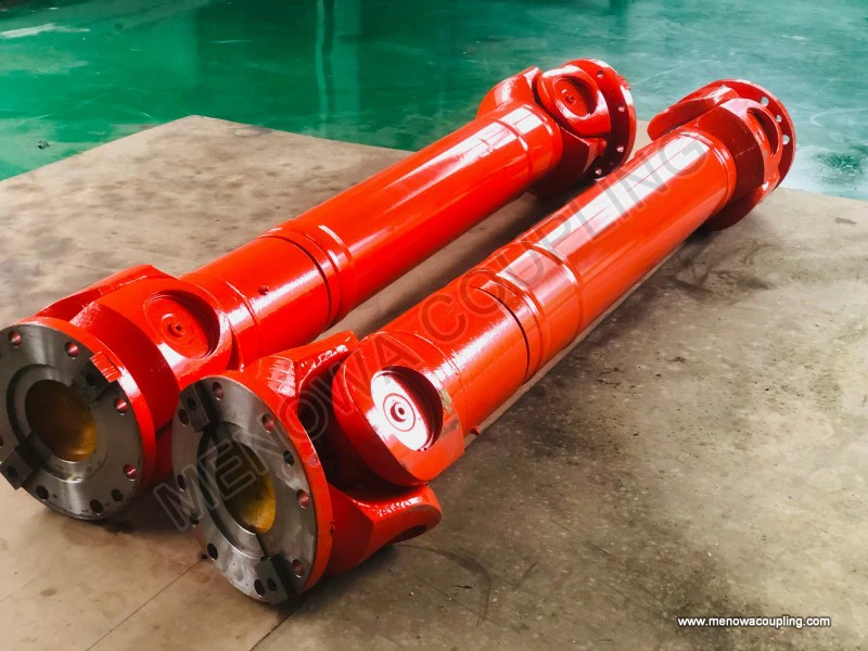
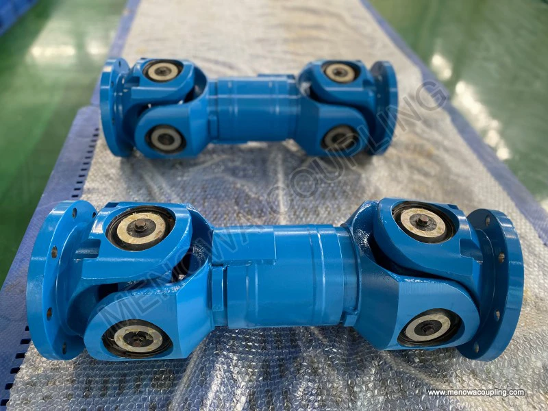
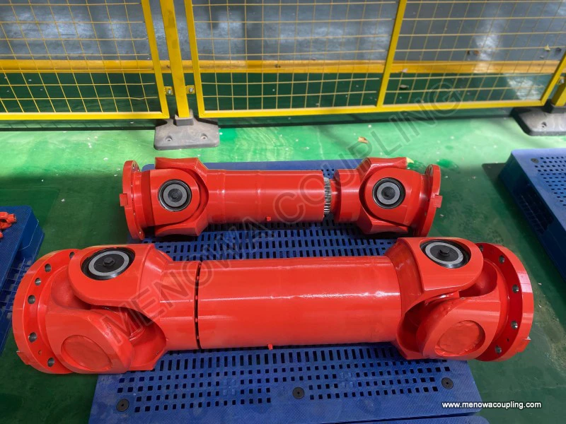
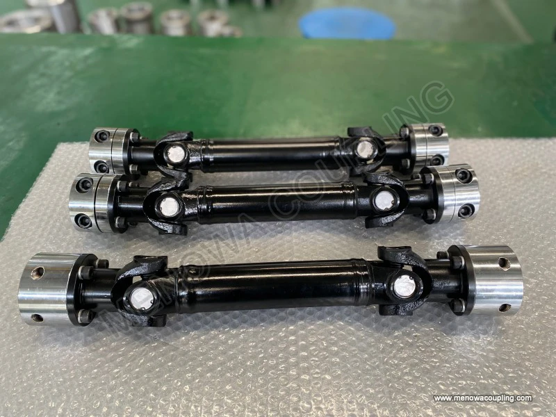
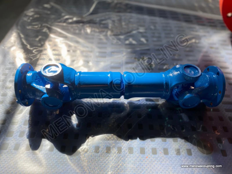
To eliminate the non-constant-speed defect of single universal coupling and realize stable constant-speed transmission under angular misalignment, the dual universal coupling transmission structure has become the mainstream optimized application form, and its working principle lies in complementary motion compensation. The dual structure is composed of two identical single universal couplings and an intermediate connecting shaft, with the two universal joints installed at the two ends of the intermediate shaft respectively. The core installation and working principle is to strictly control the spatial installation angle and phase of the two joints: ensure that the misalignment angles between the driving shaft and the intermediate shaft, and between the intermediate shaft and the driven shaft are completely equal, and make the yoke planes of the two universal joints maintain a symmetrical parallel state. Through this structural layout, the periodic speed fluctuation generated by the first universal joint during power transmission can be completely offset and compensated by the opposite speed fluctuation generated by the second universal joint.
In the working process of the dual universal coupling structure, the intermediate shaft produces regular speed fluctuation under the drive of the front-end driving joint, but the rear-end driven joint converts the fluctuating speed motion of the intermediate shaft into uniform and stable rotational motion again. The two sets of non-constant-speed motion processes with opposite phases and equal amplitudes cancel each other out, ultimately realizing that the instantaneous angular velocity of the final output driven shaft is completely consistent with that of the input driving shaft, achieving real constant-speed power transmission. At the same time, this dual-joint structure can bear a larger angular misalignment range than a single joint, and has stronger adaptability to shaft position deviation caused by equipment installation errors, mechanical vibration and thermal deformation during operation. It is the most widely used structural form in industrial precision transmission scenarios.
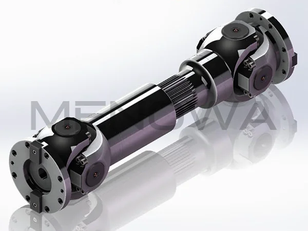
In addition to the core speed transmission and compensation principles, the universal coupling also has excellent dynamic adaptation and load transmission characteristics in actual operation. Its hinged flexible connection structure can effectively buffer and absorb instantaneous impact load during power transmission. When the mechanical system starts, stops or bears sudden load changes, the spatial swinging margin of the cross spider and the gap coordination of rotating parts can avoid rigid impact between the driving and driven shafts, protect the transmission components from instantaneous overload damage, and improve the overall stability and fatigue resistance of the transmission system. Meanwhile, the structural design allows the coupling to adapt to tiny axial telescoping and radial displacement of the two shafts while compensating for angular misalignment. This multi-dimensional displacement adaptation capability enables it to cope with various complex installation errors and dynamic position changes during equipment operation, which cannot be realized by traditional rigid transmission structures.
The mechanical efficiency and loss mechanism of universal coupling transmission are also important parts of its working principle. During normal operation, the power loss mainly comes from the friction resistance of the rotating auxiliary parts between the cross spider and the yokes, as well as the slight inertial resistance generated by the spatial swinging motion of the cross components. Under the condition of small misalignment angle and stable operation, the friction loss is extremely low, and the transmission efficiency can remain at a high level. With the increase of the misalignment angle and operating speed, the frequency and amplitude of the spatial swinging motion of the cross spider increase continuously, the relative friction stroke between matching parts increases, and the inertial loss of component motion rises accordingly, resulting in a slight decrease in transmission efficiency. However, compared with the flexible adaptability it provides, the limited power loss is completely acceptable in most industrial application scenarios, which also explains why universal couplings have outstanding comprehensive mechanical performance advantages.
In practical mechanical operation, the working state of the universal coupling is always dynamically adjusted with the operating conditions. For mechanical equipment with variable working angles, the cross spider can continuously adjust its spatial attitude in real time according to the changing misalignment angle between the two shafts, always maintaining effective hinge connection and stable power transmission. For the cyclic swing and angle change of the transmission shaft caused by mechanical movement, the coupling can follow the motion trajectory to complete adaptive deformation and position compensation without interfering with the normal power output of the system. This passive adaptive working mode does not require additional control mechanisms, relying entirely on the inherent spatial kinematic characteristics of the mechanical structure to realize flexible transmission, which is the core advantage of its simple structure, reliable performance and wide applicability.
In summary, the working principle of the universal coupling is based on the spatial multi-degree-of-freedom hinge kinematics and force transmission theory. The single-joint structure realizes flexible power transmission under angular misalignment through the cooperative rotation and swing of the cross spider and double yokes, with an inherent periodic non-constant-speed transmission characteristic; the optimized dual-joint structure realizes full compensation of speed fluctuation through phase symmetry and angle matching, achieving high-precision constant-speed transmission. Combined with its unique impact buffering, multi-dimensional displacement compensation and dynamic adaptive capabilities, the universal coupling perfectly solves the transmission difficulties of non-coaxial rotating shafts. Its simple and reliable mechanical working mechanism, excellent environmental adaptability and stable transmission performance make it a key basic component connecting power sources and executing mechanisms in various mechanical systems, providing stable and efficient power guarantee for the normal operation of diverse mechanical equipment.
Post Date: Jun 3, 2026
https://www.menowacoupling.com/china-coupling/working-principle-of-universal-coupling.html
Products
Tags
Supply
Related Articles
Universal Coupling Exporter
As a vital component in mechanical transmission systems, universal couplings play an irreplaceable role in connecting two shafts that are not in the same axis or have relative displacement, ensuring stable and efficient torque transmission. For universal coupling exporters, understanding the product’s working principle…Gap Chart of Universal Coupling
The operational stability and transmission accuracy of universal couplings are fundamentally determined by the internal gap distribution between mating components, making gap chart analysis a core technical method for evaluating assembly quality, predicting operating performance, and optimizing structural design. A univ…Universal Coupling For Ball Mill
In the complex and demanding operating environment of mineral processing, building materials production, chemical raw material grinding and other heavy industrial fields, ball mills stand as core processing equipment responsible for crushing and grinding various bulk raw materials into fine particles and powders that me…Maintenance of Universal Coupling
Universal couplings serve as indispensable connecting components in mechanical transmission systems, designed to transmit rotational torque between two shafts that operate with angular misalignment, parallel offset, or variable positional relationships. Widely applied in industrial transmission equipment, mechanical eng…Characteristics of Universal Coupling
A universal coupling, also commonly referred to as a universal joint or U-joint, is a critical mechanical component designed to connect two rigid shafts whose axes are inclined to each other, enabling the transmission of rotary motion and torque even when the shafts are not perfectly aligned. This versatile component ha…Types of Universal Coupling
In the complex and interconnected mechanical transmission systems that power modern industrial production, automotive operation, engineering machinery movement, and various precision mechanical equipment, universal couplings stand as indispensable basic mechanical components that undertake the core task of transmitting …Material of Universal Coupling
Universal couplings serve as indispensable mechanical transmission components in modern industrial and mechanical systems, dedicated to transmitting torque and rotational power between two misaligned rotating shafts. Their core operational value lies in adapting to angular deviation, axial displacement and radial offset…Universal Coupling For Sale
A universal coupling, also commonly referred to as a universal joint or U-joint, is a critical mechanical component designed to connect two rigid shafts whose axes are inclined to each other, enabling the transmission of rotary motion and torque even when there is a misalignment between the two shafts. This versatile co…Parts of Universal Coupling
A universal coupling, widely recognized as a flexible mechanical transmission component, serves as a critical connection between two rotating shafts in diverse mechanical systems. Its core value lies in its ability to transmit continuous torque and rotational motion while accommodating angular misalignment, axial displa…Classification of Universal Coupling
Universal couplings are indispensable mechanical transmission components widely applied in modern mechanical systems, serving the core function of transmitting rotational torque and motion between two shafts with angular misalignment, parallel offset, or axial displacement. Unlike rigid couplings that require precise sh…
 WeChat
 WhatsApp