Classification of Universal Coupling
Universal couplings are indispensable mechanical transmission components widely applied in modern mechanical systems, serving the core function of transmitting rotational torque and motion between two shafts with angular misalignment, parallel offset, or axial displacement. Unlike rigid couplings that require precise shaft alignment and elastic couplings focused on vibration buffering, universal couplings feature unique angular compensation capabilities, enabling stable power transmission under dynamic and complex operating conditions. With the continuous development of mechanical manufacturing technology and the diversification of industrial application scenarios, universal couplings have derived multiple structural forms with distinct performance differences. Scientific classification of universal couplings based on structural characteristics, transmission principles, motion properties and load-bearing modes helps clarify their functional advantages and applicable boundaries, providing a reliable theoretical basis for mechanical design selection, equipment assembly and operational maintenance. Throughout the development history of transmission machinery, the structural evolution of universal couplings has always centered on solving the core contradictions between transmission stability, angular compensation range, load-bearing capacity and operating speed, and different classification dimensions accurately reflect the technical characteristics and application positioning of various coupling types.
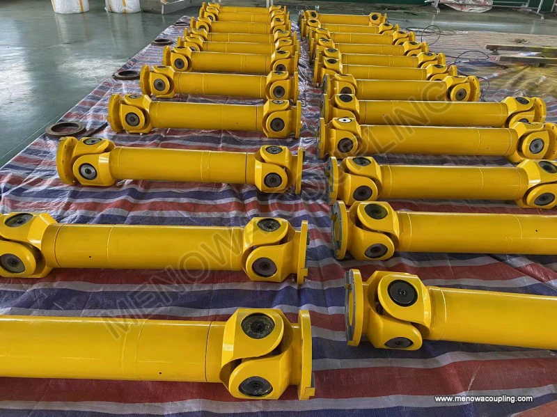
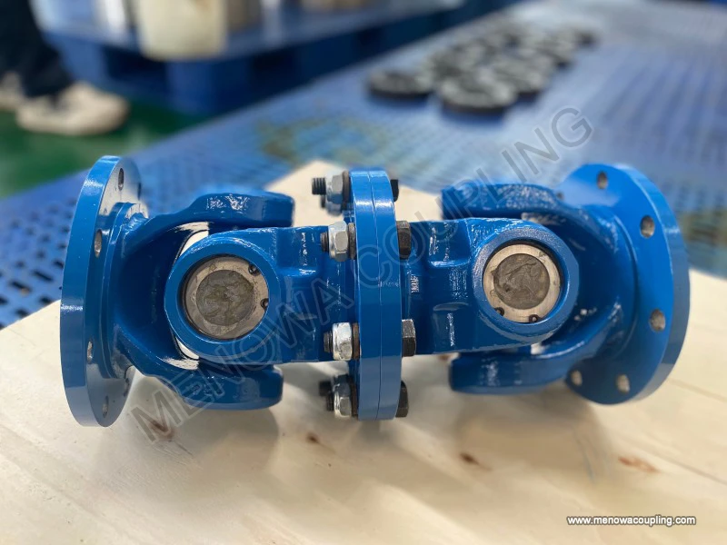
The most fundamental and widely adopted classification standard for universal couplings is based on transmission motion characteristics, which divides them into non-constant velocity universal couplings and constant velocity universal couplings. This classification dimension directly determines the dynamic transmission performance of the coupling and is the primary basis for engineering application selection. Non-constant velocity universal couplings, also known as ordinary universal couplings, are the earliest developed and most structurally mature type of universal coupling. Their core structural feature is the adoption of a cross-axis hinge connection structure, composed of two shaft yokes and an intermediate cross spider, where the cross spider is hinged with the two yokes respectively to form a mutually perpendicular rotation pair. This structural design allows the two connected shafts to form a certain included angle and realize rotational motion transmission. However, restricted by the spatial motion principle of the single cross-axis structure, this type of coupling has an inherent periodic velocity fluctuation during operation. When the driving shaft rotates at a constant speed, the angular velocity of the driven shaft will produce regular alternating changes within a single rotation cycle, and the fluctuation amplitude is positively correlated with the misalignment angle between the two shafts. The larger the angular deviation, the more obvious the velocity unevenness, which will generate corresponding dynamic load, vibration and impact on the transmission system.
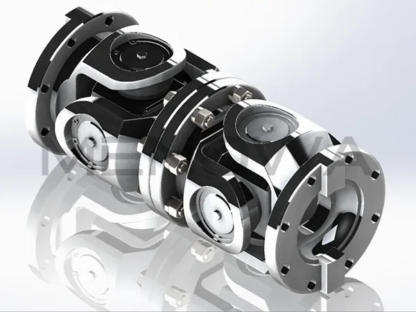
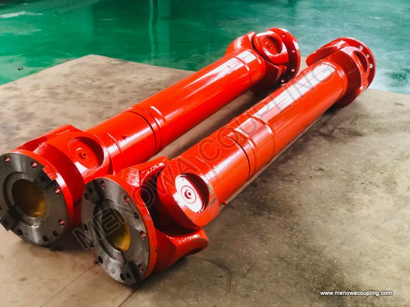
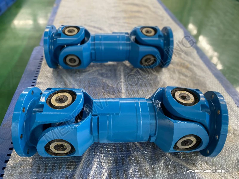
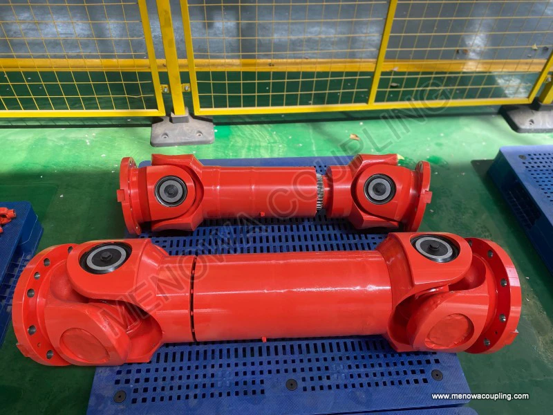
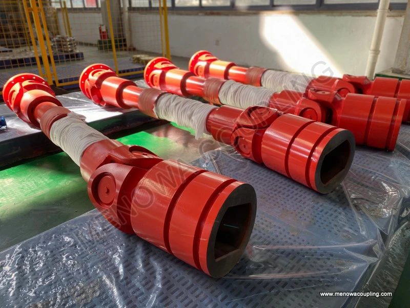
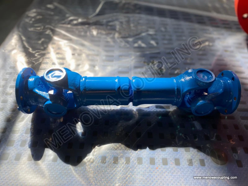
Despite the inherent non-constant velocity transmission characteristic, non-constant velocity universal couplings occupy an important position in the industrial field by virtue of their simple structure, high structural rigidity, strong overload resistance and low manufacturing and maintenance difficulty. According to the number of hinge units and overall structural layout, non-constant velocity universal couplings can be further subdivided into single cross-axis universal couplings and double cross-axis universal couplings. A single cross-axis universal coupling consists of only one group of cross-axis hinge mechanisms, with a compact overall structure and small installation space occupation. It can adapt to a maximum angular misalignment of about 45 degrees and is suitable for low-speed, medium-load transmission scenarios with low requirements for transmission stability. However, its obvious velocity fluctuation makes it unsuitable for high-speed rotating equipment and transmission systems requiring precise motion synchronization. A double cross-axis universal coupling is formed by connecting two single cross-axis hinge mechanisms in series through an intermediate shaft and an intermediate yoke. By reasonably setting the spatial installation angle of the two groups of hinges, the velocity fluctuation generated by the front hinge can be completely offset by the rear hinge, realizing approximate constant velocity transmission between the input shaft and the output shaft. This structural optimization not only retains the advantages of large angular compensation and strong load-bearing capacity of cross-axis couplings, but also effectively improves transmission stability, greatly expanding its application range. Double cross-axis universal couplings are widely used in medium and low-speed heavy-duty transmission equipment such as engineering machinery transmission shafts, metallurgical rolling equipment and agricultural machinery transmission systems, and can adapt to complex working conditions with frequent angular displacement changes and impact loads.
Constant velocity universal couplings are a special type of universal coupling developed to solve the velocity fluctuation problem of ordinary cross-axis couplings, which can realize strictly equal angular velocity transmission between the driving shaft and the driven shaft under any allowable angular misalignment conditions. Different from the hinge rotation principle of cross-axis couplings, constant velocity universal couplings mainly rely on special rolling body transmission structures to realize synchronous motion, eliminating periodic dynamic load and vibration fundamentally. According to different structural forms and rolling body types, constant velocity universal couplings are mainly divided into ball cage universal couplings, ball fork universal couplings and tripod universal couplings, each with unique structural characteristics and performance advantages. Ball cage universal couplings are composed of an outer race, an inner race, a steel ball group and a ball cage retainer. The curved raceways designed on the inner and outer races can make multiple steel balls bear load simultaneously and always operate on the bisector plane of the shaft misalignment angle during rotation, ensuring constant velocity transmission. This type of coupling has small rotation resistance, high transmission precision, low vibration and noise, and can adapt to high-speed rotating working conditions, with a maximum applicable angular misalignment of about 30 degrees. It is mostly used in high-precision and high-speed transmission scenarios such as automobile front drive half shafts and precision industrial transmission equipment.
Ball fork universal couplings adopt a simpler ball hinge structure, with spherical grooves processed on the matching surfaces of the two fork bodies, and steel balls embedded in the grooves to realize rolling transmission. The structure eliminates the complex cage structure, featuring more compact layout, higher structural rigidity and stronger wear resistance. It can maintain stable constant velocity transmission under large angular misalignment and heavy load conditions, and has better adaptability to impact loads and variable load working conditions. Tripod universal couplings take the triangular tripod frame and roller structure as the core, and the rollers can slide freely along the axial direction of the raceway while realizing rotational torque transmission, which not only meets the requirements of angular misalignment compensation, but also has excellent axial displacement compensation capability. This unique structural characteristic makes it particularly suitable for transmission systems with simultaneous angular deviation and axial telescopic displacement, and it is widely applied in the transmission parts of mobile mechanical equipment.
In addition to the core classification based on motion characteristics, universal couplings can also be classified according to structural rigidity and load-bearing adaptation characteristics, which is more targeted for industrial heavy-duty and special working condition applications. This classification method divides universal couplings into rigid universal couplings and flexible universal couplings. Rigid universal couplings are represented by cross-axis universal couplings and integral structural constant velocity couplings. All transmission components adopt rigid mechanical matching structures, with no elastic deformation parts in the transmission process. Their outstanding advantages are high transmission efficiency, strong torque rigidity and excellent heavy-load bearing performance, which can accurately transmit rotational motion and torque without obvious elastic hysteresis. However, the disadvantage is that they have no vibration damping and buffering capacity, and the vibration and impact generated by the equipment during operation will be directly transmitted along the shaft system, which may cause fatigue wear of parts in long-term operation. Such couplings are mainly suitable for fixed industrial equipment, heavy machinery and low-vibration transmission systems with stable working conditions.
Flexible universal couplings are improved and optimized on the basis of traditional rigid universal structures, adding elastic buffer components in the transmission link. While retaining the angular compensation function of universal couplings, they obtain good vibration damping and noise reduction performance. The elastic components can absorb part of the impact load and vibration energy during transmission, reduce the dynamic stress of shaft parts, and effectively extend the service life of the transmission system. Different from pure rigid couplings, flexible universal couplings sacrifice part of transmission rigidity to obtain better dynamic stability, and are more suitable for variable load, frequent start-stop and high-vibration working scenarios. In practical classification, flexible universal couplings mostly appear in the derivative forms of small and medium-load universal couplings, and are widely used in light industrial machinery, intelligent equipment and vehicle auxiliary transmission systems that require both displacement compensation and vibration reduction.
From the perspective of structural integration and processing form, universal couplings can be divided into split type and integral type, which is an important classification basis affecting installation convenience and structural stability. Split universal couplings adopt a split yoke structure, which is connected and fixed by fasteners during assembly. This structural design has outstanding advantages in installation and maintenance: it does not need to disassemble the whole shaft system during assembly and replacement, with low operation difficulty and strong equipment adaptability. However, the split structure has inevitable assembly gaps, which may produce slight structural looseness after long-term operation under alternating loads, affecting transmission precision to a certain extent. Integral universal couplings adopt an integral forging or casting integrated molding process for the yoke and shaft body, with no assembly gaps inside the structure, high overall rigidity and good structural stability. The integral structure can withstand greater alternating torque and impact load, with higher transmission precision and longer service life. The disadvantage is that the installation and disassembly process is cumbersome, and the whole coupling needs to be disassembled and replaced during maintenance, which is suitable for fixed high-precision and heavy-duty transmission equipment that does not require frequent disassembly.
In terms of operating speed adaptation, universal couplings can be classified into low-speed heavy-duty type, medium-speed universal type and high-speed precision type, which corresponds to the graded application requirements of modern mechanical equipment. Low-speed heavy-duty universal couplings are mostly cross-axis rigid structures, with thickened component sections and high material strength, focusing on improving load-bearing capacity and impact resistance, and allowing certain velocity fluctuation and vibration. They are mainly used in low-speed operation links of heavy equipment such as mining machinery, metallurgical equipment and large cranes. Medium-speed universal couplings balance load-bearing performance and transmission stability, mostly adopting optimized double cross-axis structures or ordinary constant velocity structures, with moderate angular compensation range and stable operation, covering most conventional industrial mechanical transmission scenarios. High-speed precision universal couplings take dynamic balance performance and transmission uniformity as the core design indicators, adopting precision-machined constant velocity structures, with strict dynamic balance treatment of components, extremely low operation vibration and velocity error, and are specially used for high-speed rotating precision equipment such as automated precision machine tools and high-speed power transmission systems.
It is worth noting that the various classification standards of universal couplings are interrelated and complementary rather than independent. A single universal coupling product often belongs to multiple classification categories at the same time. For example, a high-precision ball cage coupling is both a constant velocity universal coupling in terms of motion characteristics and an integral high-speed precision universal coupling in terms of structure and speed adaptation. In engineering practice, it is necessary to comprehensively judge and select the appropriate coupling type according to the actual working conditions such as shaft misalignment angle, operating speed, load type, vibration environment and maintenance requirements. The diversified classification system of universal couplings reflects the perfect matching degree between mechanical transmission components and industrial application scenarios. With the progress of material technology and structural optimization design, new types of universal couplings with higher precision, stronger adaptability and longer life continue to emerge, and the classification system is also constantly enriched and improved. Mastering the classification logic and performance characteristics of different universal couplings is of great significance for optimizing the design of mechanical transmission systems, improving equipment operation efficiency and reducing equipment failure rates, and lays a solid foundation for the stable and efficient operation of various mechanical equipment.
Post Date: May 26, 2026
https://www.menowacoupling.com/china-coupling/classification-of-universal-coupling.html
Products
Tags
Supply
Related Articles
Universal Coupling Factory
In the intricate ecosystem of modern mechanical transmission systems, universal couplings stand out as indispensable foundational components, serving as the critical bridge that connects rotating shafts and ensures stable power transmission across complex operating conditions. As core mechanical parts designed to resolv…Material of Universal Coupling
Universal couplings serve as indispensable mechanical transmission components in modern industrial and mechanical systems, dedicated to transmitting torque and rotational power between two misaligned rotating shafts. Their core operational value lies in adapting to angular deviation, axial displacement and radial offset…Universal Coupling For Sale
A universal coupling, also commonly referred to as a universal joint or U-joint, is a critical mechanical component designed to connect two rigid shafts whose axes are inclined to each other, enabling the transmission of rotary motion and torque even when there is a misalignment between the two shafts. This versatile co…Universal Coupling Price
Universal coupling manufacture stands as a sophisticated and precise mechanical production discipline focused on crafting flexible transmission components that serve as critical connecting parts in mechanical power systems. These specialized mechanical structures are designed to transmit rotational torque and motion bet…Parts of Universal Coupling
A universal coupling, widely recognized as a flexible mechanical transmission component, serves as a critical connection between two rotating shafts in diverse mechanical systems. Its core value lies in its ability to transmit continuous torque and rotational motion while accommodating angular misalignment, axial displa…Universal Coupling Manufacture
In the complex landscape of mechanical power transmission, universal couplings stand out as indispensable components that bridge the gap between misaligned shafts, enabling the seamless transfer of torque and rotational motion across a wide range of industrial and mechanical applications. Unlike rigid couplings that dem…
 WeChat
 WhatsApp