Gap Chart of Universal Coupling
The operational stability and transmission accuracy of universal couplings are fundamentally determined by the internal gap distribution between mating components, making gap chart analysis a core technical method for evaluating assembly quality, predicting operating performance, and optimizing structural design. A universal coupling, as a key flexible transmission component designed to connect two non-coaxial or dynamically offset rotating shafts, relies on controllable internal gaps to achieve angular deflection, axial displacement, and radial deviation compensation during power transmission. Unlike rigid transmission structures that pursue zero clearance fit, universal couplings require reasonable and graded gaps between cross shafts, bearing components, fork joints, and telescopic structures to accommodate mechanical displacement and thermal deformation, while excessive or uneven gaps will directly trigger vibration, noise, transmission lag, and accelerated component wear. The gap chart intuitively quantifies the dimensional tolerance, assembly clearance range, and dynamic gap variation of each key matching part of the universal coupling, forming a systematic data reference for production assembly, equipment debugging, and daily operation maintenance, and running through the whole life cycle of coupling design, manufacturing, and application.
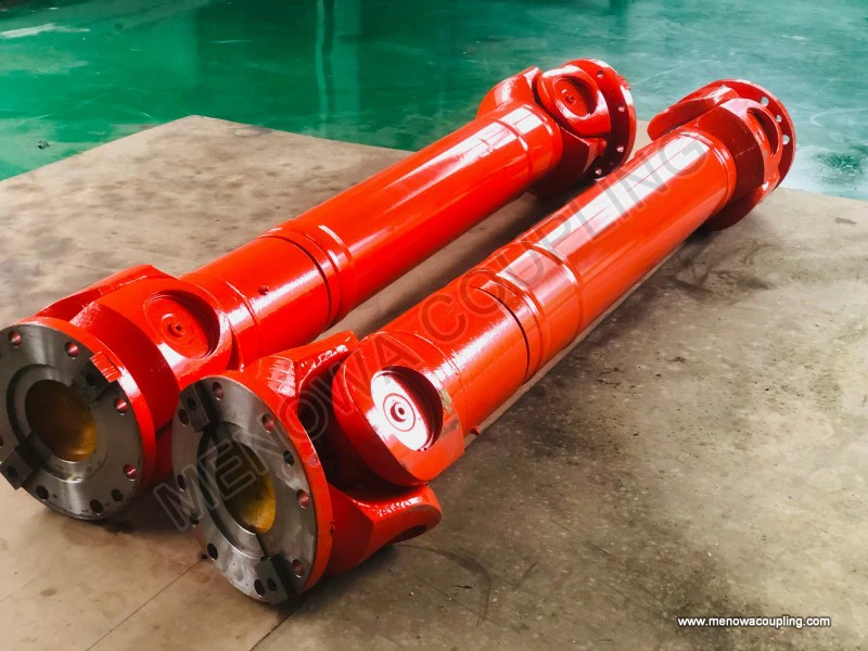
To understand the practical value of a universal coupling gap chart, it is first necessary to clarify the classification and formation mechanism of internal gaps, which constitute the core data framework of the gap chart. The gaps of universal couplings are mainly divided into static assembly gaps and dynamic operating gaps, both of which are recorded and analyzed in detail in the standardized gap chart. Static assembly gaps refer to the fixed dimensional differences between matching components under static, room-temperature, and no-load conditions, including the fitting gap between the cross shaft journal and the inner ring of the rolling bearing, the assembly gap between the bearing outer ring and the fork joint hole, and the matching gap of the telescopic spline pair. These gaps are preset based on structural design and manufacturing tolerance standards, serving as the basic guarantee for the flexible movement of the coupling. Dynamic operating gaps, by contrast, are variable gaps generated under working conditions such as torque loading, high-speed rotation, and temperature rise, which change in real time with load fluctuation, rotational speed variation, and component thermal expansion and contraction. The gap chart integrates static fixed gap parameters and dynamic variable gap ranges, and records the gap variation rules under different working conditions, forming a comprehensive evaluation system for coupling matching performance.
The static gap data in the universal coupling gap chart is the foundation of overall performance evaluation, with each key gap index corresponding to specific assembly functions and structural characteristics. The journal-bearing fitting gap is one of the most critical static gaps. The cross shaft, as the core force-transmitting component of the universal coupling, realizes rotational deflection through the matching of four journals and bearings. A tiny reasonable gap here can ensure flexible rotation of the cross shaft without jamming during angular compensation, while an undersized gap will cause friction and abrasion of the journal surface due to insufficient lubrication space, and an oversized gap will lead to radial shaking of the cross shaft and reduce transmission stability. Another key static gap is the bearing-fork joint assembly gap. The bearing unit fixed in the fork joint hole needs a moderate gap to adapt to the micro-deformation of the fork joint under load and avoid bearing extrusion deformation. Meanwhile, the spline matching gap of the telescopic section is an important index for axial displacement compensation. The gap chart clearly marks the standard range of spline gaps, which can ensure the coupling freely stretches and contracts to absorb axial displacement generated by equipment operation, installation deviation, or mechanical vibration, and prevent transmission jitter caused by excessive spline clearance or telescopic failure caused by too small clearance.
Dynamic gap data is the most valuable part of the universal coupling gap chart for practical engineering applications, reflecting the real performance state of the coupling in actual operation. When the universal coupling transmits torque, the contact pressure between components changes with the load magnitude, which will cause micro-displacement and elastic deformation of matching parts, thus changing the internal gap value. Under low-load and low-speed operating conditions, the dynamic gap is close to the static assembly gap, with small variation range and stable transmission state. With the increase of torque and rotational speed, the load-bearing components undergo elastic compression, the local gap of the force-bearing side decreases, while the gap of the non-force-bearing side increases, forming asymmetric gap distribution. The gap chart records the dynamic gap variation gradient corresponding to different torque levels and rotational speed intervals, and summarizes the threshold range of stable gap operation. In addition, temperature change is an important factor affecting dynamic gaps. Continuous high-speed operation will generate friction heat, causing thermal expansion of metal components and reducing internal gaps. Long-term low-temperature operation will lead to component shrinkage and increased gaps. The complete gap chart incorporates temperature compensation coefficients, realizing accurate correction of gap values under different ambient temperatures and working heat conditions.
The gap chart also systematically sorts out the adverse effects of abnormal gap values on the working performance of universal couplings, providing a clear fault judgment basis for engineering operation. When the overall gap is lower than the standard range, the fitting between components is too tight, the lubricating oil film between moving pairs is difficult to form stably, dry friction occurs between journals and bearings, and the friction resistance of rotation increases significantly. This state will lead to increased transmission power consumption, local overheating of the coupling, and accelerated wear of the cross shaft and bearing surfaces. In severe cases, it will cause component jamming, failure of angular displacement compensation, and even shaft system locking. When the overall gap exceeds the standard range, the internal matching looseness of the coupling increases, and obvious rotation angle hysteresis will occur during torque transmission. Each start and stop of the equipment will produce impact vibration due to excessive gap clearance, resulting in periodic noise of the transmission system. Long-term operation with excessive gaps will aggravate the fatigue wear of splines, bearings, and cross shaft surfaces, reduce the overall rigidity of the coupling, and cause deviation of transmission accuracy, which further affects the synchronous operation precision of the entire mechanical equipment.
Different structural types of universal couplings have differentiated standard gap ranges, which are fully reflected in the classified gap chart system. Traditional cross-axis universal couplings, which are widely used in heavy-load mechanical transmission, have relatively large allowable gap ranges because they need to bear large torque and realize large-angle deflection compensation. Their gap design focuses on meeting the requirements of structural deformation and displacement compensation under heavy load, with higher tolerance for dynamic gap fluctuation. Constant-velocity universal couplings applied in high-precision transmission scenarios adopt stricter gap control standards, with smaller static assembly gaps and narrower dynamic gap variation ranges. This precise gap matching design can effectively eliminate transmission speed fluctuation and angle error, ensuring constant-speed and high-precision power transmission under variable deflection angles. Telescopic universal couplings used for long-distance shaft connection have independent gap standards for spline pairs, focusing on balancing the flexibility of axial telescopic movement and the stability of torque transmission, avoiding axial jitter or transmission lag caused by unreasonable spline gaps.
In industrial production and equipment maintenance, the gap chart of universal couplings has formed standardized application logic, covering product quality inspection, equipment installation and debugging, and fault diagnosis and maintenance. In the manufacturing and assembling stage, workers compare the measured assembly gap data with the standard values in the gap chart to screen qualified products, eliminate unqualified couplings with excessive or insufficient local gaps, and ensure that each batch of products meets the structural matching requirements. In the equipment installation stage, technicians adjust the assembly tightness of the coupling according to the gap chart parameters, optimize the gap distribution state according to the actual installation offset and working condition requirements, and make targeted gap compensation for installation deviation, so as to maximize the adaptive performance of the coupling. In the daily operation and maintenance stage, staff can regularly detect the internal gap of the coupling, compare the detected data with the dynamic gap curve in the gap chart, judge the wear degree and performance attenuation state of components, and predict potential faults such as bearing aging, spline wear, and cross shaft deformation in advance, so as to carry out targeted maintenance and replacement and avoid equipment shutdown failure caused by gap failure.
Further analysis of the gap chart data can summarize the optimization direction of universal coupling structural design and process manufacturing. By counting the gap failure frequency of different parts in the long-term operation data, it can be found that the bearing-journal matching part and the spline pair matching part are the most prone to gap failure. Based on the gap variation rules, manufacturers can optimize the manufacturing tolerance standard of key components, appropriately adjust the static gap reserved value according to the working condition characteristics, and adopt fine finishing processes to improve the surface accuracy of matching parts, reduce uneven gap distribution caused by processing errors. In terms of assembly process optimization, the gap chart provides graded assembly standards for different working scenarios. For high-speed and high-precision transmission equipment, strict small-gap assembly standards are adopted; for heavy-load and low-speed industrial equipment, moderate large-gap assembly parameters are selected to adapt to large deformation and displacement compensation requirements. In addition, the gap dynamic variation law in the chart can guide the optimization of lubrication schemes. Reasonable gap matching is matched with corresponding lubricating grease viscosity and filling amount, which can maintain stable oil film lubrication in the gap range of component movement, reduce friction and wear, and extend the service life of the coupling.
In practical engineering applications, the gap chart of universal couplings also needs to be dynamically calibrated according to service life and working environment. With the extension of service time, the surface wear of coupling components will lead to continuous increase of internal gaps, and the gap variation rate corresponds to the aging degree of the equipment. The gap chart can establish a life prediction model by recording the gap variation data of couplings with different service years, providing a basis for formulating scientific component replacement cycles. For couplings working in harsh environments such as high dust, high humidity, and corrosive media, the gap variation amplitude is larger than that of conventional working conditions due to external erosion and particle wear. The modified gap chart for special working environments can accurately evaluate the working state of couplings under complex conditions and avoid performance misjudgment caused by ignoring environmental interference factors.
In conclusion, the gap chart is an indispensable technical tool for the performance evaluation, quality control, and intelligent maintenance of universal couplings. It systematically digitizes the complex internal matching relationship and dynamic variation law of couplings, turns the fuzzy assembly matching experience into standardized and quantifiable technical parameters, and provides accurate data support for all links from product design and manufacturing to engineering application and fault maintenance. Reasonable application and dynamic optimization of the gap chart can effectively improve the transmission stability, operation accuracy and service life of universal couplings, reduce equipment operation failure rate and maintenance cost, and provide a reliable technical guarantee for the efficient and stable operation of various mechanical transmission systems. With the continuous upgrading of mechanical transmission technology, the gap chart of universal couplings will further develop towards refinement, dynamization and intelligentization, and its data accuracy and application scope will be continuously expanded to adapt to the higher precision and higher reliability working requirements of modern mechanical equipment.
Post Date: May 26, 2026
https://www.menowacoupling.com/china-coupling/gap-chart-of-universal-coupling.html
Products
Tags
Supply
Related Articles
Universal Coupling Supplier
In the complex and interconnected system of modern mechanical transmission equipment, universal couplings stand out as one of the most fundamental and indispensable functional components, serving as a critical bridge for power and motion transmission between rotating shafts in diverse mechanical structures. Unlike rigid…Structure of Universal Coupling
A universal coupling, widely recognized as a core mechanical transmission component in modern machinery systems, serves as a flexible connection device designed to transmit rotational torque and motion between two shafts that present angular, parallel, or axial misalignment. Its unique structural configuration enables s…Components of Universal Coupling
A universal coupling, widely known as a universal joint or Cardan joint, is a fundamental mechanical transmission component designed to transmit torque and rotational motion between two shafts that exhibit angular misalignment, parallel offset, or axial displacement. Unlike rigid couplings that require precise shaft ali…Universal Coupling Supply
In the intricate ecosystem of mechanical power transmission, universal couplings stand out as indispensable foundational components that bridge the functional gaps of traditional rigid connection structures. Serving as a core link between rotating shafts in mechanical systems, these mechanical devices are engineered to …Uses of Universal Coupling
In the intricate ecosystem of mechanical transmission systems, universal couplings stand out as one of the most versatile and indispensable mechanical components, serving as a critical bridge for power and motion transmission across countless industrial and civilian mechanical devices. Also widely known as universal joi…Diagram of Universal Coupling
A universal coupling, widely recognized as a core mechanical component for flexible power transmission, serves as a pivotal connecting structure in mechanical transmission systems to transfer rotational torque and motion between two shafts with angular misalignment. The structural diagram of a universal coupling intuiti…
 WeChat
 WhatsApp