Cardan Joint Drive Shaft
In the entire field of mechanical power transmission, the cardan joint drive shaft stands as one of the most foundational and widely applied mechanical components, undertaking the essential task of transmitting rotational torque and mechanical power between two mechanical shafts that cannot maintain perfect coaxial alignment in various working scenarios. Unlike rigid transmission shafts that only adapt to linear and coaxial power delivery, the cardan joint drive shaft integrates flexible connection structures based on cardan joint design, which can effectively compensate for angular deviation, axial displacement and small radial misalignment between the driving end and the driven end during equipment operation. This unique adaptive performance makes it an indispensable core part across automotive transmission systems, engineering machinery transmission assemblies, industrial production equipment transmission lines, agricultural machinery power connection structures and many other mechanical equipment configurations. The development history of the cardan joint drive shaft can be traced back to the early research on gimbal mechanisms by ancient mechanical scholars, and after centuries of structural iteration, material upgrading and mechanical principle optimization, it has evolved from simple manual mechanical connection parts to precision engineered transmission components that can adapt to high-speed rotation, heavy-load operation and complex alternating working conditions. Its inherent mechanical characteristics and structural design logic determine the overall operating stability, power transmission efficiency and service life of the entire mechanical driveline system, and mastering the internal working mechanism, structural composition characteristics and practical application matching rules of the cardan joint drive shaft is of great significance for mechanical equipment design, daily operation management and later maintenance and upkeep.
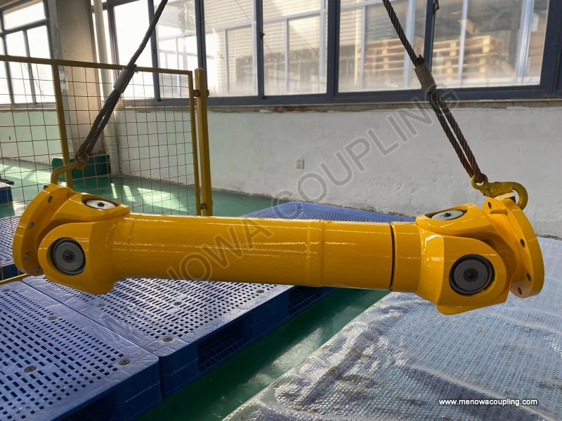
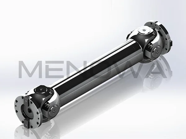
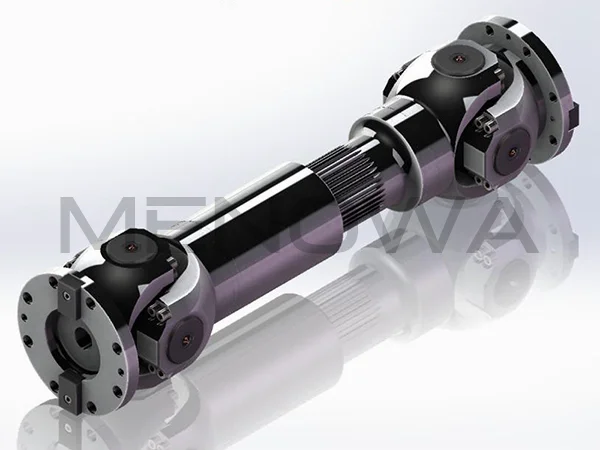
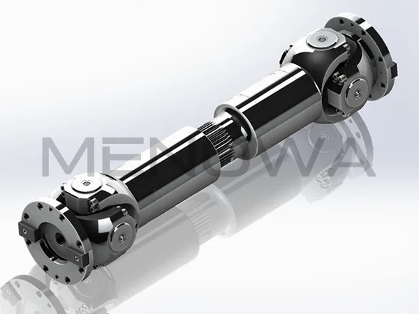
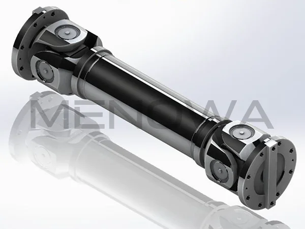
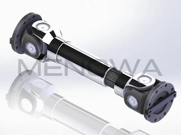
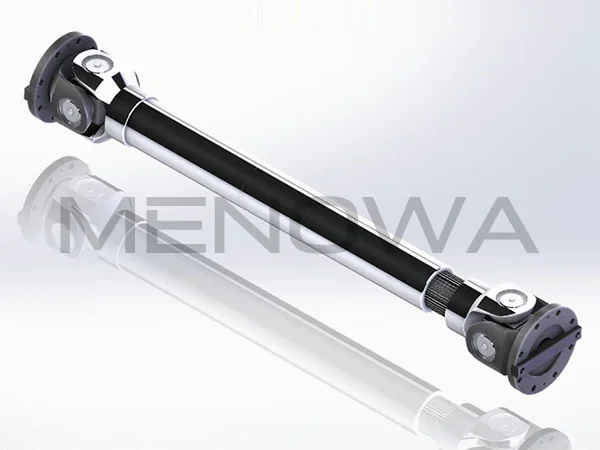
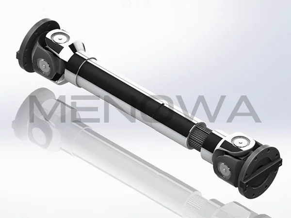
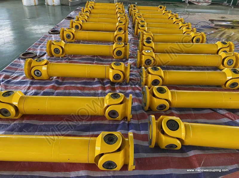
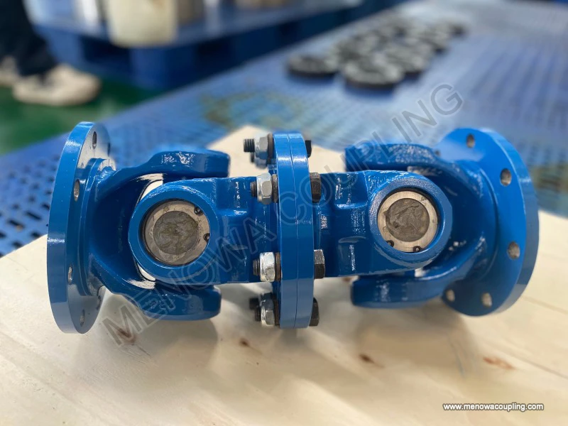
The basic composition of the cardan joint drive shaft follows a mature and stable mechanical structural logic, and each component inside the assembly bears distinct functional responsibilities, forming a coordinated and linked overall transmission structure through precise assembly and mechanical matching. The core functional unit of the entire assembly is the cardan universal joint, which is also the key structural part that endows the drive shaft with angular deviation compensation capability. A single cardan joint is mainly composed of two symmetrically distributed joint yokes, a cross-shaped intermediate connecting part commonly referred to as a cross spider, and a set of rotating bearing assemblies matched with each trunnion of the cross spider. The two joint yokes are respectively connected to the driving shaft body and the driven shaft body, and the four cylindrical trunnions distributed at the four ends of the cross spider are movably installed inside the mounting holes of the two joint yokes through bearing structures. The bearing assemblies mostly adopt needle roller bearing structures with compact layout and strong load-bearing capacity, which can reduce the friction resistance generated during the relative rotation between the cross spider and the joint yokes, while bearing the radial torque and axial alternating load generated during power transmission. Outside the bearing parts, there are usually sealing and dustproof structural accessories, which can isolate external dust, moisture, particulate impurities and other pollutants from the internal moving friction pairs, and prevent the loss of internal lubricating grease, creating a stable lubrication and operating environment for the long-term rotation of the cardan joint. The main shaft body of the cardan joint drive shaft is usually made of high-strength alloy steel materials processed by forging and precision machining, with a hollow tubular structure adopted in most mainstream designs. This hollow shaft body structure can effectively reduce the overall weight of the drive shaft assembly while ensuring sufficient torsional rigidity and structural strength, avoiding additional energy consumption caused by excessive self-weight during high-speed rotation, and reducing the centrifugal force generated by the shaft body during operation to ensure the smoothness of high-speed power transmission. At both ends of the shaft body and the connecting position with the cardan joint, there are flange connection structures or integrated forging connection sections, which realize stable fixed assembly between the shaft body and the joint yokes through fasteners, ensuring that no relative displacement or loosening occurs at the connection position during long-term torque transmission and alternating load impact. In addition to the core cardan joint and main shaft body, a complete cardan joint drive shaft is also equipped with telescopic slip joint structures in many application scenarios. This auxiliary structure can adapt to the axial distance change between the driving end power output part and the driven end power input part caused by equipment vibration, mechanical operation displacement and component deformation during the working process, avoiding additional tensile stress or compressive stress on the drive shaft assembly caused by fixed axial distance, and further improving the adaptive capacity of the entire transmission system to complex working condition changes.
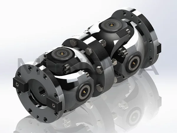
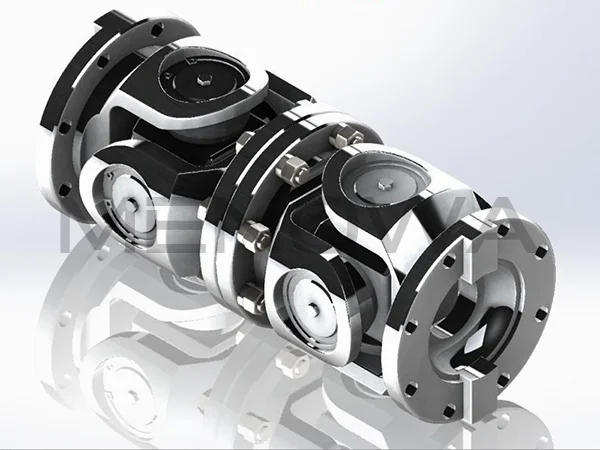
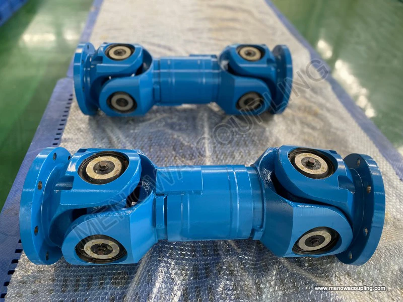
The working principle of the cardan joint drive shaft is based on the spatial geometric motion characteristics of the cross spider and the relative rotation coordination relationship between the joint yokes, realizing continuous and stable torque transmission under the premise of allowing a certain angular included angle between the driving shaft and the driven shaft. When the power source drives the driving joint yoke to rotate around the axis of the driving shaft, the rotational motion and torque will be transmitted to the cross spider through the bearing assembly on one side of the cardan joint, and the cross spider will drive the driven joint yoke to rotate synchronously through the bearing assembly on the other side, thus completing the power transmission from the driving end to the driven end. The key mechanical feature of a single cardan joint in the transmission process is the non-constant velocity transmission characteristic, which means that when there is a certain angular deviation between the driving shaft and the driven shaft, the instantaneous rotational speed of the driven shaft will produce periodic fluctuation changes within each rotation cycle even if the driving shaft maintains a constant rotational speed. The magnitude of this instantaneous speed fluctuation is closely related to the size of the angular included angle between the two shafts; the larger the angular deviation, the more obvious the periodic change of the instantaneous speed of the driven shaft, and the more intense the additional mechanical vibration and torsional vibration generated during transmission. The fundamental cause of this non-constant velocity characteristic lies in the spatial motion trajectory difference between the two sets of joint yokes and the cross spider. In the rotation process of the driving joint yoke, the effective rotation radius of the cross spider in the driving plane and the driven plane changes periodically, resulting in the periodic change of the torque transmission efficiency and rotation driving effect in a single rotation cycle. Although the single cardan joint has the inherent non-constant velocity transmission defect, this problem can be effectively solved by adopting a double cardan joint matching design in the actual drive shaft assembly. The double cardan joint structure connects two single cardan joints in series through an intermediate short shaft, and by reasonably adjusting the installation angle and spatial position of the two cardan joints, the speed fluctuation generated by the first cardan joint can be completely offset by the reverse speed fluctuation generated by the second cardan joint. Through this coordinated structural design, the final output rotational speed of the driven shaft can maintain a stable and constant state, realizing the overall constant velocity power transmission effect of the entire cardan joint drive shaft assembly. This structural design method not only retains the angular deviation compensation advantage of the cardan joint drive shaft, but also eliminates the adverse effects of speed fluctuation, vibration and impact caused by non-constant velocity transmission, making the drive shaft suitable for high-speed and stable power transmission working scenarios.
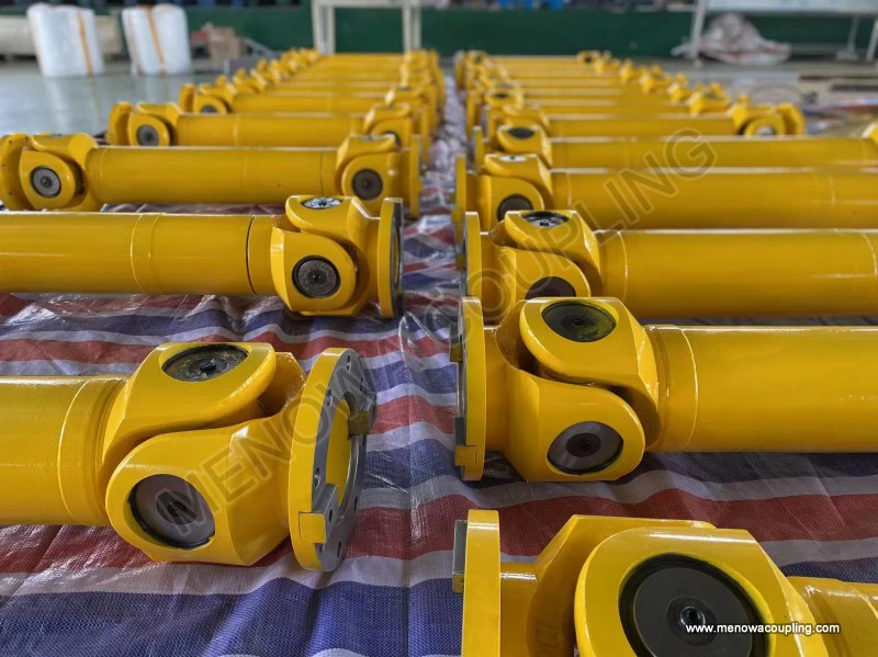
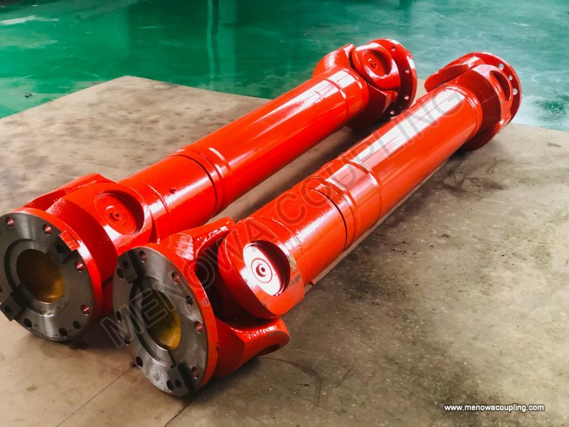
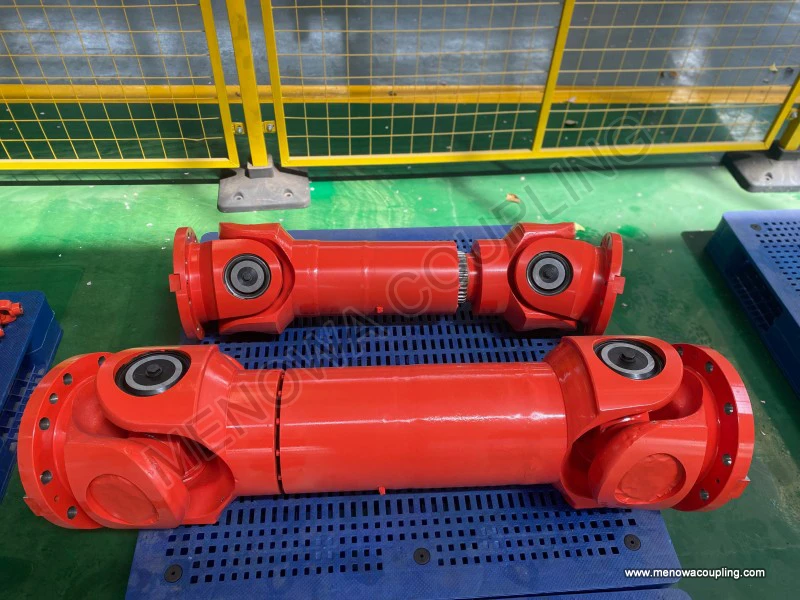
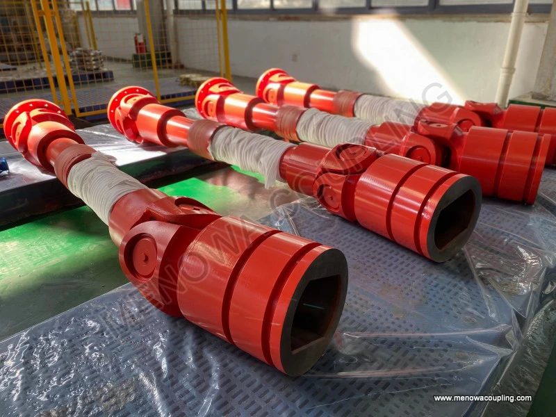
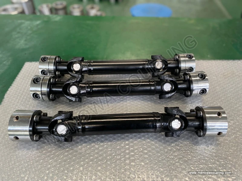
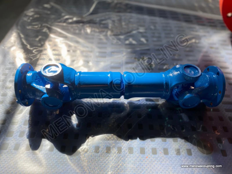
In practical mechanical configuration and equipment application, cardan joint drive shafts are divided into multiple structural types according to different load-bearing requirements, rotational speed ranges, angular deviation adaptation ranges and installation space conditions, and each structural type has targeted application scenarios and design adaptation characteristics. The most basic single cardan joint drive shaft is simple in overall structure, low in manufacturing and assembly difficulty, and small in occupied installation space, and is mostly used in low-speed operation, light-load transmission and small angular deviation working environments. This type of drive shaft is often applied to small-sized auxiliary mechanical equipment, low-power agricultural machinery auxiliary transmission parts and some simple industrial conveyor power connection structures. Due to the inherent non-constant velocity transmission characteristic, it is not suitable for equipment that requires high rotation stability and long-term continuous operation, and its working angular deviation is usually controlled within a small range to reduce vibration and wear caused by speed fluctuation. The double cardan joint drive shaft, as the most widely used mainstream structural form, has excellent constant velocity transmission performance and large angular deviation adaptation capability, and can work stably under the working condition that the included angle between the driving shaft and the driven shaft reaches a relatively large range. This type of drive shaft is widely used in passenger vehicles, commercial vehicles, heavy engineering machinery and medium and large-scale industrial transmission equipment. In automotive rear-wheel drive and four-wheel drive systems, the double cardan joint drive shaft is responsible for transmitting the power output by the transmission to the rear axle differential. During the driving process of the vehicle, the chassis suspension will produce up and down jitter and displacement changes with the road surface bumps, resulting in continuous changes in the relative position and angular deviation between the transmission and the rear axle. The double cardan joint drive shaft can adapt to this dynamic position change in real time, ensuring continuous and stable power transmission without obvious vibration and power loss. In addition to the single and double cardan joint structural forms, there are also heavy-duty reinforced cardan joint drive shafts designed for ultra-heavy load and harsh working conditions. This type of drive shaft adopts thickened cross spider structure, enlarged-size bearing assembly, high-strength forging shaft body and reinforced flange connection structure, and undergoes special heat treatment process to improve the overall torsional strength, impact resistance and fatigue resistance. It is mainly used in heavy mining machinery, large construction equipment, metallurgical industrial transmission lines and other mechanical scenarios with heavy load impact, frequent start and stop operation and harsh external working environment, and can maintain stable transmission performance and structural reliability under long-term high-strength working conditions.
The matching design and parameter selection of cardan joint drive shafts need to comprehensively consider multiple key factors such as equipment power parameters, working rotation speed, load characteristics, installation space limit and working environment conditions, and scientific and reasonable design matching is the premise to ensure the efficient and stable operation of the drive shaft and extend its service life. First of all, the torsional torque borne by the drive shaft in the working process is the core basis for structural size design and material selection. Different mechanical equipment has different rated working torque and instantaneous impact torque in the power transmission process. The instantaneous impact torque generated during equipment start-up, sudden load change and mechanical collision is often much higher than the rated working torque, so the design and selection of the cardan joint drive shaft need to take the impact torque into account, and set a reasonable safety factor to avoid structural deformation, component fracture and failure of the drive shaft under impact load. Secondly, the working rotation speed directly affects the dynamic balance performance and centrifugal force effect of the drive shaft. When the drive shaft runs at high speed, the unbalanced mass of the shaft body and the cardan joint components will generate centrifugal force, causing mechanical vibration and noise, and accelerating the wear of bearing and rotating friction pairs. Therefore, high-speed applied cardan joint drive shafts need to undergo precision dynamic balance calibration treatment after processing and assembly, strictly controlling the unbalanced amount of the entire assembly to ensure the stability of high-speed operation. The angular deviation range between the driving shaft and the driven shaft in actual work is also a key design parameter. Different cardan joint structures have different allowable working angular ranges, and exceeding the rated angular deviation will lead to increased transmission friction, intensified speed fluctuation, rapid component wear and even direct damage to the cardan joint structure. In the design and installation stage, it is necessary to reasonably set the installation position and structural layout of the drive shaft according to the maximum angular deviation generated during equipment operation, ensuring that the actual working angle is always within the allowable safe range. In addition, the working environment has an important impact on the material selection and structural protection design of the drive shaft. For equipment working in humid, corrosive, dusty and high-temperature environments, the cardan joint drive shaft needs to adopt corrosion-resistant alloy materials and enhanced sealing and dustproof structures, and the surface of the shaft body and components needs to be treated with anti-rust and anti-corrosion processes to prevent component corrosion, lubrication failure and structural performance degradation caused by adverse environmental factors.
In the long-term continuous operation process of mechanical equipment, the cardan joint drive shaft will inevitably produce various forms of performance attenuation and component wear due to mechanical friction, alternating load impact, material fatigue aging and environmental erosion, and understanding the main failure forms and root causes is crucial for daily equipment management and fault prevention. The most common failure form of the cardan joint drive shaft is the wear and failure of the cardan joint bearing assembly. The needle roller bearings inside the cardan joint are in a long-term rotating friction working state, bearing radial torque, axial load and alternating impact load for a long time. If the lubricating grease deteriorates, loses efficacy or is insufficiently supplemented for a long time, the friction resistance between the needle roller and the bearing seat will increase sharply, resulting in dry friction wear. Long-term dry friction will lead to the wear and deformation of the bearing inner and outer rings and needle roller falling off, making the cardan joint produce abnormal rotation resistance, obvious mechanical vibration and abnormal noise during operation. In severe cases, the bearing will be stuck and locked, resulting in the interruption of power transmission and equipment shutdown failure. Another common failure form is the fatigue fracture of the cross spider and the shaft body structure. The cardan joint drive shaft bears periodic alternating torsional load during operation, and the structural parts such as the cross spider and the shaft body are in a state of repeated stress cycle for a long time. With the increase of working time, material fatigue cracks will gradually appear at the stress concentration positions of the components. Under the continuous action of alternating load, the cracks will gradually expand, and finally lead to fatigue fracture of the components, resulting in the complete failure of the drive shaft transmission function. Loosening of the connection fasteners at the flange connection position is also a frequent problem in the operation process. Due to long-term equipment vibration and load impact, the connecting bolts and fixing parts at the flange position will gradually loosen, resulting in relative displacement between the drive shaft and the connecting end parts, causing abnormal vibration, torque transmission attenuation and even connection separation in serious cases. In addition, the aging and damage of the sealing and dustproof structure will lead to the entry of external impurities and the loss of lubricating grease, which will indirectly accelerate the wear and failure of the internal moving parts of the cardan joint, forming a vicious cycle of performance attenuation of the entire drive shaft assembly.
Scientific and standardized daily maintenance and regular overhaul work can effectively reduce the failure probability of the cardan joint drive shaft, delay the wear and aging speed of components, and significantly extend the overall service life of the drive shaft assembly, ensuring the long-term stable and efficient operation of the mechanical transmission system. The core content of daily maintenance is the regular inspection and replenishment of lubricating grease for the cardan joint parts. Lubricating grease is the key medium to reduce friction and wear between the internal moving friction pairs of the cardan joint, and also plays a role in heat dissipation, vibration reduction and auxiliary sealing. According to different working intensity and environmental conditions, regular grease injection and replacement should be carried out for the cardan joint bearings and rotating parts to ensure that the internal friction pairs are always in a good lubrication state. Before grease injection, the dust and dirt at the grease injection port should be cleaned to prevent external impurities from being brought into the inside of the joint with the grease, avoiding abrasive wear of the bearing components. The regular inspection work should include checking the tightness of all flange connection fasteners, observing whether there is loosening, missing or corrosion of bolts, and tightening and replacing the fasteners in time if abnormal conditions are found. At the same time, it is necessary to regularly check the integrity of the sealing and dustproof accessories of the cardan joint and the telescopic slip joint structure, and replace the aging, damaged and failed sealing parts in a timely manner to ensure the isolation protection effect of the internal moving structure. In the regular overhaul work with longer cycle, the overall operation state of the drive shaft should be comprehensively detected, including checking whether there is abnormal vibration and abnormal noise during the rotation process, detecting the dynamic balance state of the drive shaft, checking the wear degree of the cross spider and bearing assembly, and inspecting whether there are fatigue cracks and deformation on the surface of the shaft body and structural parts. For the worn and aging components that have reached the service limit, they should be replaced in time instead of continuing to be used with faults, so as to avoid small faults evolving into major equipment failures and affecting the normal production and operation of the entire mechanical equipment. In addition, during the daily operation of the equipment, avoid long-term overload operation and frequent sudden start and stop operation as much as possible, reduce the instantaneous impact load on the cardan joint drive shaft, and reduce the fatigue loss and structural wear of the drive shaft assembly from the source.
With the continuous progress of mechanical manufacturing technology, material science and mechanical design optimization concepts, the cardan joint drive shaft industry is also undergoing continuous technological iteration and performance upgrading, and the development direction is mainly concentrated on new material application, structural optimization design, lightweight manufacturing and intelligent state monitoring. In terms of material application, traditional ordinary carbon steel is gradually replaced by high-strength alloy steel, wear-resistant forged steel and new composite structural materials. These new materials have higher torsional strength, better fatigue resistance and corrosion resistance, and can reduce the overall structural weight of the drive shaft while improving the load-bearing capacity and service life, realizing the dual optimization of lightweight and high performance. In terms of structural optimization design, through finite element mechanical simulation analysis, the stress concentration positions of the traditional cardan joint drive shaft structure are optimized and improved, the structural size layout is adjusted, the mechanical transmission efficiency is improved, and the structural wear and vibration generated during operation are reduced. The optimized structural design can further improve the angular deviation adaptation range and transmission stability of the drive shaft, and adapt to more complex and diverse working condition requirements. In terms of manufacturing technology, precision forging, CNC precision machining and automatic assembly technology are widely used in the production and processing of cardan joint drive shafts, improving the dimensional accuracy and assembly matching degree of components, reducing assembly errors and mechanical unbalanced quantity, and laying a foundation for the stable operation of the drive shaft under high-speed and heavy-load conditions. In recent years, with the development of intelligent mechanical equipment, some cardan joint drive shaft assemblies have begun to be equipped with built-in vibration sensors, temperature sensors and wear monitoring sensing components. These intelligent monitoring devices can collect the operating vibration data, working temperature data and component wear state data of the drive shaft in real time during the operation process, and transmit the data to the equipment control system. Through data analysis and early warning judgment, potential fault hidden dangers of the drive shaft can be found in advance, realizing predictive maintenance of the drive shaft, avoiding sudden equipment shutdown failures, and improving the overall operation reliability and maintenance efficiency of the mechanical transmission system.
Looking at the entire mechanical power transmission industry, the cardan joint drive shaft, as a classic and continuously evolving mechanical transmission component, will always occupy an irreplaceable core position in various mechanical equipment fields relying on its unique angular deviation compensation performance, reliable power transmission capacity and wide working condition adaptability. Whether in traditional automotive transmission systems, engineering machinery and agricultural machinery equipment, or in emerging industrial intelligent production lines and special mechanical transmission devices, the cardan joint drive shaft undertakes the basic and core power transmission work, and its operating state is directly related to the overall working efficiency, operation stability and service life of the mechanical equipment. From the initial simple mechanical gimbal structure to the modern precision intelligent drive shaft assembly after centuries of development and iteration, the technological progress of the cardan joint drive shaft always follows the basic demand of mechanical power transmission, constantly optimizing structural performance, improving material quality, upgrading manufacturing technology and innovating maintenance and management methods. In the future, with the continuous development of high-end mechanical equipment, intelligent manufacturing technology and new material technology, the comprehensive performance of the cardan joint drive shaft will be further improved, the application scope will be further expanded, and it will continue to provide stable, efficient and reliable power transmission support for the development of various mechanical industries. At the same time, in the process of equipment design, application and maintenance, only by deeply understanding the structural characteristics, working principle, failure mechanism and maintenance essentials of the cardan joint drive shaft, can we give full play to its excellent transmission performance, ensure the long-term safe and stable operation of mechanical equipment, and create more stable operation benefits for various mechanical production and application scenarios.
https://www.menowacoupling.com/industrial-coupling/cardan-joint-drive-shaft.html
 WeChat
 WhatsApp