Gear Type Coupling
In the entire field of mechanical power transmission systems, the connection and coordination between rotating shafts are indispensable basic links that determine the stable operation, power transmission efficiency and long-term service cycle of the entire mechanical equipment. Various types of shaft connection components have been developed and optimized according to different working conditions, load characteristics and operating environment requirements, among which gear type coupling has always occupied a crucial position in heavy-duty mechanical transmission scenarios by virtue of its unique structural design, excellent torque bearing capacity and reliable misalignment compensation performance. As a key flexible rigid transmission component integrating mechanical gear meshing principle and shaft displacement adjustment function, gear type coupling is different from ordinary elastic couplings that rely on elastic deformation for buffering and simple rigid couplings that cannot adapt to shaft position deviation. It balances the high rigidity required for efficient torque transmission and the flexibility needed to adapt to various inevitable shaft misalignments in actual operation, making it widely used in metallurgical production, mineral exploitation, marine power propulsion, heavy engineering machinery, industrial production conveying equipment and many other core industrial fields. Understanding the internal structural composition, inherent working mechanism, core performance characteristics, correct selection logic, standardized installation and commissioning methods, as well as scientific daily maintenance and fault troubleshooting measures of gear type coupling is not only a necessary prerequisite for mechanical design personnel to carry out reasonable equipment system matching design, but also an important guarantee for equipment operation and maintenance personnel to extend the service life of transmission components, reduce equipment downtime and control overall mechanical operation and maintenance costs.
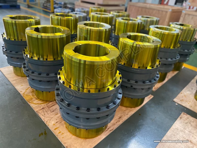
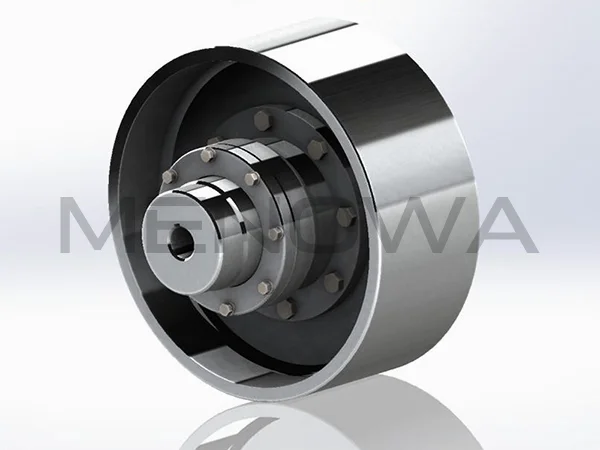
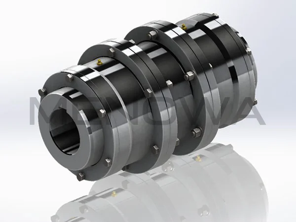
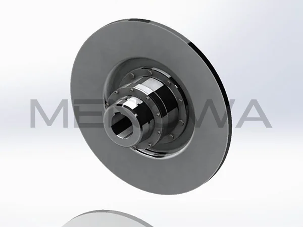
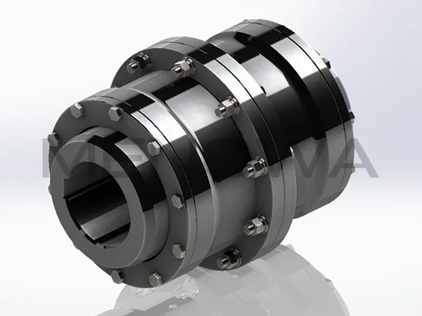
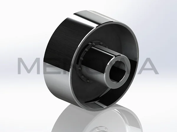
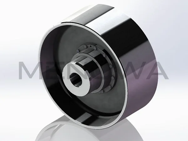
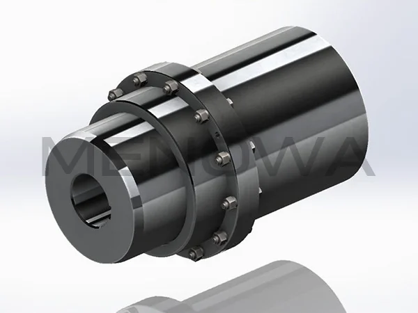
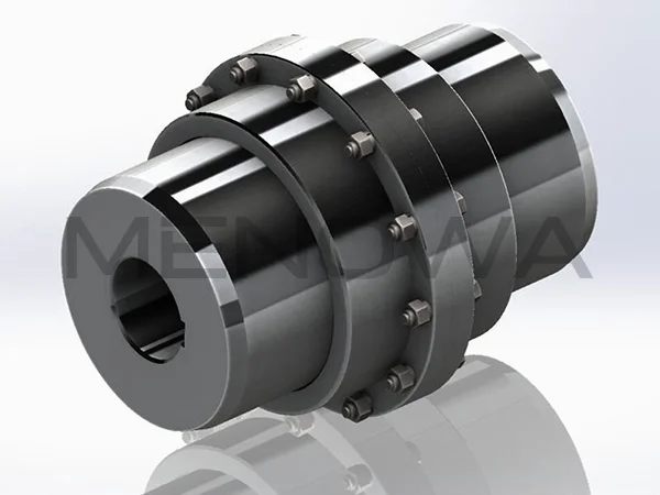
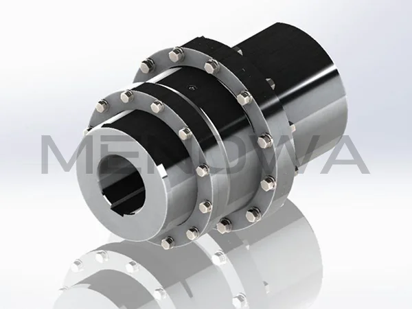
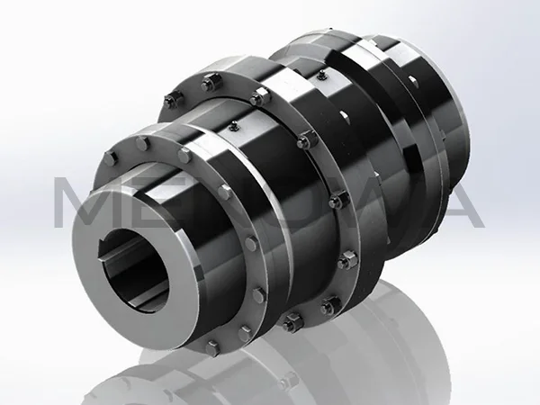
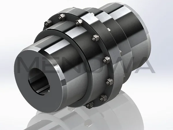
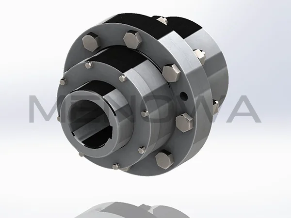
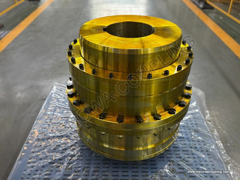
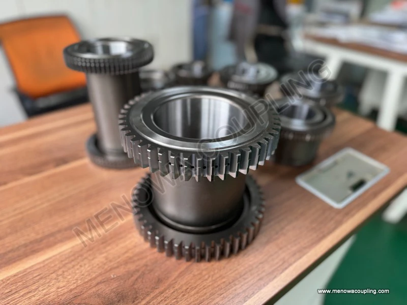
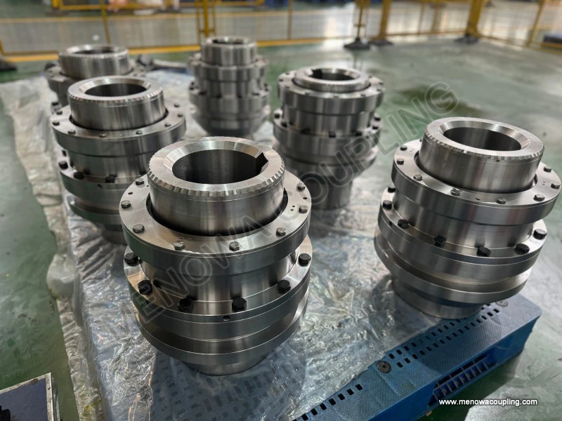
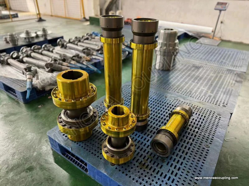
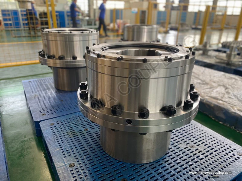
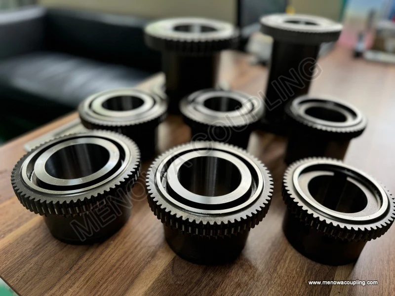
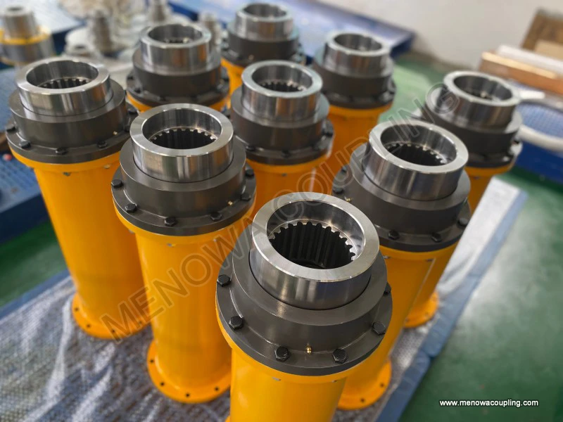
The basic composition of gear type coupling follows the mature mechanical transmission design logic formed after long-term industrial practice, and each component has clear functional division and mutual coordination relationship, without redundant structural design, and all structural settings are centered around efficient torque transmission and reliable misalignment compensation. The main body of a standard gear type coupling is composed of two independent inner gear hubs with external gear teeth, two outer gear sleeves with internal gear teeth, connecting bolt assemblies, sealing protection parts and optional spacer components according to actual installation needs. The two inner gear hubs are the core connecting parts directly connected with the driving shaft and the driven shaft respectively, and are usually fixedly sleeved on the shaft body through key connection structures or interference assembly methods. The external gear teeth processed on the outer circular surface of the inner gear hub adopt special tooth profile crowning processing technology, which is the key structural design to realize the flexible adaptation of the coupling to various shaft displacements. The outer gear sleeves are arranged on the outer side of the two inner gear hubs in a matching manner, the internal gear teeth processed on the inner wall of the outer sleeve mesh with the external gear teeth of the inner hub one by one to form a stable gear meshing transmission pair, and the two outer gear sleeves are tightly connected as a whole through high-strength bolt groups, so that the torque transmitted by the driving shaft can be smoothly transferred from one inner hub to the other inner hub through the meshing action of internal and external gear teeth, and finally transmitted to the driven shaft to complete the whole power transmission process. The sealing parts installed at the assembly gap between the inner hub and the outer sleeve play a vital protective role in the normal operation of the gear type coupling. These sealing structures can effectively isolate external dust, moisture, corrosive impurities and other harmful substances from entering the internal gear meshing area, and at the same time prevent the internal lubricating medium from leaking outwards, ensuring that the gear meshing part can always be in a stable and effective lubrication state during long-term operation. The optional spacer components are mainly applied to mechanical equipment scenarios where the distance between the driving shaft and the driven shaft is relatively large, which can meet the installation and transmission requirements of long-distance shaft connection without changing the basic transmission performance and structural stability of the gear type coupling.
The working principle of gear type coupling is based on the basic mechanical meshing transmission principle of gears, but it is quite different from the fixed-axis gear transmission used in gearboxes and speed change devices in traditional mechanical equipment. Ordinary fixed-axis gear transmission focuses on maintaining precise transmission ratio and fixed relative position between gears, while the gear meshing design of gear type coupling abandons the limit of fixed meshing position and reserves reasonable meshing gap and displacement allowance on the basis of ensuring stable torque transmission. When the mechanical equipment starts to operate, the driving shaft drives the connected inner gear hub to rotate synchronously, and the external gear teeth on the inner hub generate continuous driving force through meshing contact with the internal gear teeth of the outer sleeve. The outer sleeve rotates synchronously under the action of gear meshing thrust, and then drives the other outer sleeve and the matched inner gear hub to rotate together through the connecting bolts, so as to realize the synchronous rotation of the driven shaft and complete the continuous transmission of torque and rotational power. The special crowned tooth profile design of the external gear teeth is the core of the coupling to realize misalignment compensation. The tooth surface crowning treatment makes the contact part of the gear teeth form a smooth curved transition structure. When relative displacement or angular deviation occurs between the driving shaft and the driven shaft due to equipment installation errors, mechanical operation vibration, component thermal deformation and other objective factors, the meshing contact position between the internal and external gear teeth can be appropriately adjusted along the curved tooth surface without generating excessive extrusion stress and friction resistance. This flexible meshing adjustment mode enables the gear type coupling to always maintain a good meshing state in the process of operation, will not cause severe gear tooth wear or transmission jamming due to shaft position deviation, and ensures the continuity and stability of power transmission while realizing automatic compensation of various misalignments.
In the actual operation process of mechanical equipment, the coaxiality between the driving shaft and the driven shaft can never reach an absolute ideal state, and various forms of misalignment are inevitable objective phenomena, which mainly include radial parallel misalignment, angular misalignment and axial displacement misalignment, and these three types of misalignment often exist in a mixed form in most mechanical transmission systems. Radial parallel misalignment refers to the situation that the center lines of the two connected shafts are parallel to each other but have a certain radial offset in the spatial position, which is usually caused by installation positioning errors, foundation settlement of equipment and slight deformation of the frame structure during long-term operation. Angular misalignment means that the center lines of the two shafts are not parallel and intersect at a certain angle, which is mostly formed by the inclination of the equipment base, thermal expansion and contraction deformation of the shaft body during high-speed operation and assembly deviation of mechanical components. Axial displacement misalignment is the relative movement of the two shafts along the axial direction, which is mainly affected by the thermal elongation of the shaft body during operation, the axial movement of bearing components and the stress deformation of the transmission system. Gear type coupling has excellent adaptive compensation ability for all these mixed misalignment states, which is far better than ordinary rigid couplings and some simple elastic couplings. The reasonable gap between the meshing gear teeth and the flexible contact characteristics brought by the crowned tooth profile allow the gear meshing pair to produce small relative sliding and displacement during operation, which can effectively offset the radial offset and angular deviation between the shafts. At the same time, the reserved axial assembly gap between the inner hub and the outer sleeve can well adapt to the axial telescopic displacement of the shaft body, avoiding additional axial stress and transmission vibration caused by axial position changes. This comprehensive misalignment compensation performance ensures that the gear type coupling will not produce additional mechanical stress on the shaft, bearing and other key components of the equipment under various non-ideal installation and operation conditions, effectively reducing the vibration and impact of the transmission system and creating a stable operating environment for the whole mechanical equipment.
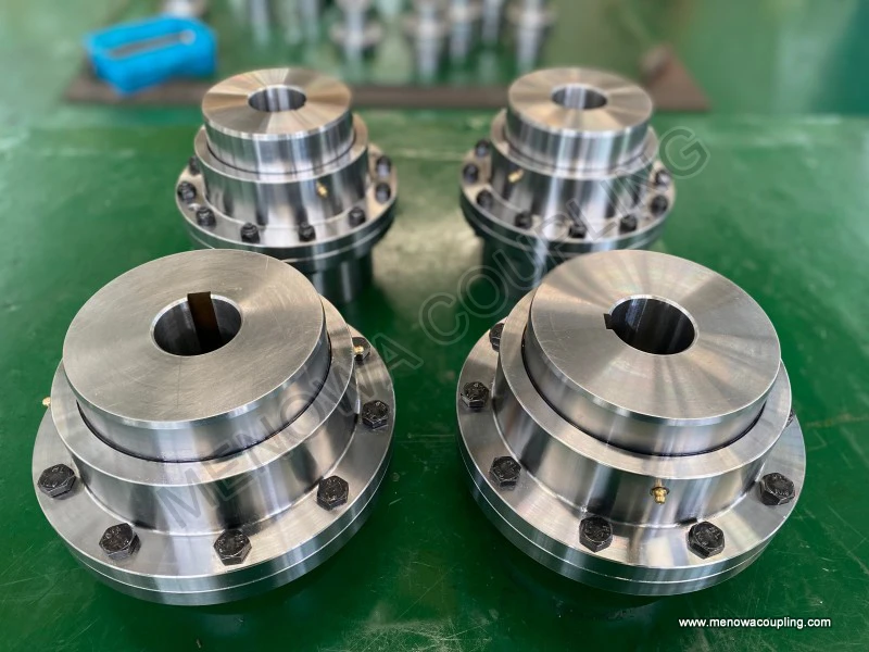
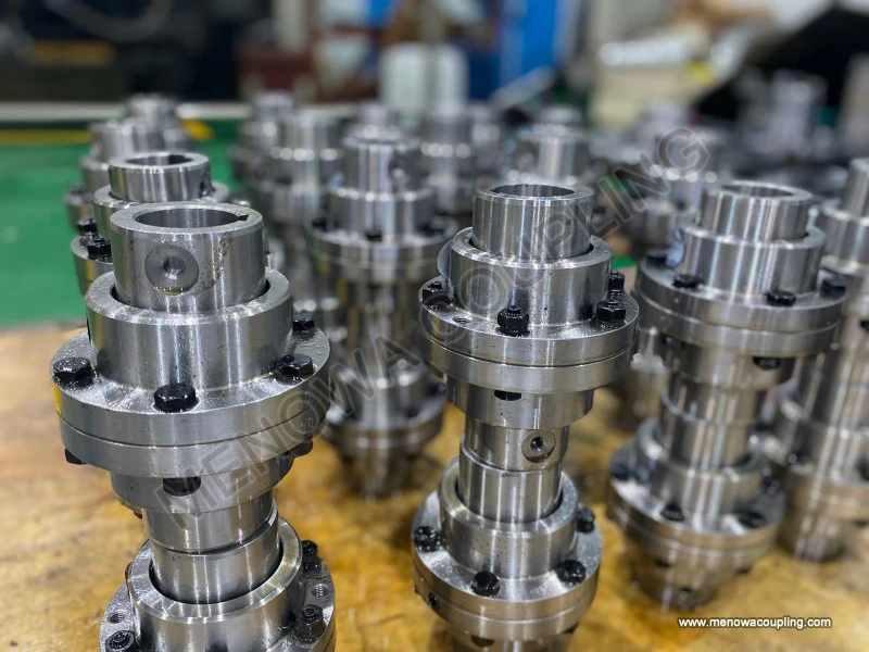
In terms of core transmission performance, gear type coupling has prominent advantages in torque bearing capacity and transmission rigidity, which makes it the preferred transmission connection component for heavy-load and high-power mechanical equipment. The torque transmission of gear type coupling is completed by the simultaneous meshing and stress bearing of multiple gear teeth. The contact stress generated by the torque load is evenly distributed on each meshing gear tooth surface through the gear meshing structure, avoiding the problem of local stress concentration caused by single-point or small-area force bearing in other types of couplings. This multi-tooth synchronous stress-bearing structure enables the gear type coupling to bear large instantaneous impact load and long-term stable heavy load, and the transmission process maintains high torsional rigidity, without obvious torsional deformation and rotation angle lag during torque transmission. High torsional rigidity is very important for mechanical equipment that requires precise power transmission and synchronous operation, because it can ensure that the rotation speed and torque output of the driving end and the driven end remain highly consistent, avoid transmission efficiency reduction and operation accuracy deviation caused by torsional deformation, and meet the operation requirements of equipment with high synchronization requirements for transmission motion. At the same time, the overall structural design of gear type coupling is compact and reasonable. Under the condition of bearing the same torque load, its overall outer diameter and axial occupied space are smaller than those of many other heavy-duty couplings, which can save the installation space of mechanical equipment and facilitate the overall structural layout and compact design of mechanical systems. Although the structure of gear type coupling is relatively compact, its overall structural strength and fatigue resistance are excellent. The main components are made of high-strength alloy materials processed by precision forging and heat treatment, which can withstand long-term cyclic load and frequent start-stop impact in industrial production, and maintain stable structural performance and transmission effect for a long time.
Compared with other common types of couplings in the mechanical industry, gear type coupling also has some inherent performance characteristics and applicable limitation rules, which need to be fully considered in the early selection and design stage. Different from elastic couplings that rely on elastic elements to absorb vibration and buffer impact, gear type coupling belongs to flexible and rigid transmission components with weak vibration absorption and buffering capacity. It cannot effectively absorb high-frequency vibration and strong impact load generated by the transmission system. Therefore, it is not suitable for mechanical equipment scenarios with severe alternating impact load and frequent violent vibration, and additional vibration reduction and buffering components need to be configured if used in such scenarios. In addition, due to the gear meshing transmission structure adopted by gear type coupling, relative sliding friction will inevitably occur between the internal and external gear teeth during operation to adapt to shaft misalignment displacement, which determines that the gear meshing part must rely on continuous and reliable lubrication to reduce friction and wear. Good lubrication conditions are the key to ensure the normal operation and long service life of gear type coupling. Once the lubrication is insufficient or the lubricating medium fails, the friction and wear of the gear tooth surface will intensify rapidly, resulting in tooth surface scratch, abrasion, even tooth surface peeling and gear tooth fracture in serious cases, which directly leads to the failure of the coupling transmission function. At the same time, the manufacturing and assembly precision requirements of gear type coupling are higher than those of ordinary simple couplings. The gear tooth processing precision, the matching precision between the inner hub and the shaft, and the assembly fastening precision of the connecting bolts all affect the transmission performance and service life of the coupling. Higher manufacturing precision ensures the stability of gear meshing operation, and standardized assembly ensures the coaxiality and connection firmness of the coupling installation, avoiding abnormal wear and vibration caused by poor assembly quality.
The scientific selection of gear type coupling is the primary link to ensure its efficient and stable operation in mechanical equipment, and the selection process needs to comprehensively consider multiple key factors related to equipment operation, rather than simply selecting according to the shaft diameter size alone. First of all, the most core selection basis is the actual torque demand of the mechanical transmission system, including the rated working torque during normal operation and the maximum instantaneous impact torque during equipment start-up, shutdown and load mutation. It is necessary to reasonably select the coupling specification with sufficient torque bearing allowance according to the actual load characteristics, to avoid long-term overload operation of the coupling resulting in accelerated fatigue damage of gear teeth and structural components. Secondly, the rotation speed range of the equipment shaft must be matched. Although gear type coupling can adapt to medium and high-speed operation conditions, different specifications of couplings have reasonable applicable rotation speed ranges. Excessively high rotation speed will increase the centrifugal force of the coupling components and the friction heat generation of gear meshing, affecting the operation stability and lubrication effect, while too low rotation speed under heavy load is easy to cause local pressure wear of gear teeth. Thirdly, the misalignment degree of the actual installation position of the driving shaft and the driven shaft needs to be measured and evaluated, and the coupling type with corresponding misalignment compensation allowance should be selected according to the actual radial offset, angular deviation and axial displacement range, to ensure that the coupling has enough adjustment space to adapt to the shaft position deviation in actual operation. In addition, the operating environment conditions of the equipment also need to be fully considered, including ambient temperature, humidity, and whether there are corrosive media, dust pollution and other adverse factors. For high-temperature operating environments, it is necessary to select high-temperature resistant lubricating media and heat-treated structural materials; for corrosive environments, it is necessary to take anti-corrosion surface treatment measures for the coupling surface to prevent structural corrosion and performance attenuation. Finally, the installation space size and maintenance convenience of the equipment should be combined to select the overall structural size and installation form of the coupling, ensuring that the coupling can be smoothly installed and disassembled, and daily maintenance and lubrication operations can be carried out conveniently in the later stage.
The standardized installation and commissioning process of gear type coupling directly affects its initial operating state and subsequent service life, and any irregular installation operation will lay hidden dangers for the long-term stable operation of the coupling and even the whole equipment. Before the formal installation, all components of the gear type coupling need to be carefully inspected, including checking whether the gear tooth surface has processing defects, scratches and damage, whether the inner hole of the inner hub is smooth and free of deformation, whether the sealing parts are complete and intact, and whether the connecting bolts meet the strength requirements. At the same time, the surface of the driving shaft and driven shaft installation position should be cleaned to remove rust, oil stain and sundries, ensuring that the assembly surface is clean and smooth, avoiding assembly deviation caused by sundry extrusion. In the formal assembly process, the two inner gear hubs should be respectively installed on the driving shaft and the driven shaft in place according to the assembly process requirements, and the fixed connection structure should be installed firmly to ensure that there is no relative rotation and axial displacement between the inner hub and the shaft. Then the outer gear sleeves are sleeved on the outer side of the inner hubs respectively, and the internal and external gear teeth are ensured to be in a natural meshing state without forced extrusion and deflection. After the preliminary assembly of all components is completed, the coaxiality calibration of the two shafts must be carried out by using professional detection tools. The calibration work needs to strictly control the radial and angular misalignment within the allowable range of the coupling design, reducing the installation deviation to the minimum limit, which can effectively reduce the abnormal friction and vibration of the gear meshing part in the later operation process. After the coaxiality calibration is qualified, the connecting bolts between the outer sleeves are fastened evenly and symmetrically in sequence, avoiding the problem of local stress concentration and assembly deformation caused by one-sided excessive fastening. After the installation and fastening are completed, the initial rotation test of the equipment should be carried out. The manual rotating shaft checks whether the coupling rotation is flexible and free of jamming and abnormal friction, and then the no-load trial operation is carried out to observe whether the coupling has abnormal vibration, noise and temperature rise, and the installation and commissioning work is completed after confirming that all operating indicators are normal.
Daily maintenance and regular lubrication management are the core measures to prolong the service life of gear type coupling and maintain its stable transmission performance, and long-term stable operation of the coupling is inseparable from scientific and standardized maintenance work throughout the whole life cycle. Lubrication maintenance is the most important part of all maintenance work. The relative sliding friction between the meshing gear teeth of gear type coupling is inevitable during operation, and the lubricating medium can form a stable oil film on the gear tooth surface, isolating the direct contact between metal gear teeth, reducing friction resistance and wear degree, and at the same time taking away the friction heat generated by gear meshing operation to avoid excessive temperature rise affecting the structural strength and material performance of components. According to different operating speed and load conditions, gear type coupling can adopt grease lubrication or oil lubrication. Grease lubrication is suitable for medium and low speed and heavy-load conventional operating scenarios, with simple maintenance and long lubrication cycle; oil lubrication is suitable for high-speed operation scenarios, with better heat dissipation and lubrication circulation effect. In the daily maintenance process, the sealing state of the coupling must be checked regularly to observe whether there is lubricant leakage at the sealing gap. Once leakage is found, the sealing parts should be replaced in time and the lubricant should be supplemented to ensure that the internal gear meshing area is always filled with sufficient lubricating medium. Regularly check the operating temperature and vibration state of the coupling during equipment operation. If abnormal temperature rise or obvious vibration and noise are found, stop the machine in time for inspection to eliminate potential faults. In addition, regular comprehensive maintenance and inspection should be carried out according to the equipment operation cycle, including checking the fastening state of connecting bolts to prevent bolt loosening caused by long-term vibration, checking the wear degree of gear tooth surface to see if there is abnormal abrasion, scratch and corrosion, and cleaning the dust and sundries outside the coupling to keep the external structure clean and well heat-dissipated. Timely maintenance and lubrication can effectively avoid most common failure problems of gear type coupling and keep its transmission performance stable for a long time.
In the long-term industrial operation process, gear type coupling may have some common failure problems due to insufficient maintenance, irregular installation, long-term overload operation and other reasons, and targeted fault analysis and timely troubleshooting can quickly restore the normal operation of the equipment and reduce production downtime. The most common failure phenomenon is excessive wear of gear tooth surface, which is mainly caused by insufficient lubrication, lubricant deterioration and failure, long-term overload operation and excessive installation misalignment. After the gear tooth surface is excessively worn, the meshing gap increases, resulting in increased vibration and noise during coupling operation, reduced transmission stability, and even torque transmission insufficiency in serious cases. For this kind of fault, the worn gear components need to be inspected and replaced in time, the lubricating medium needs to be updated, and the shaft coaxiality needs to be recalibrated to eliminate excessive misalignment. Another common fault is loosening of connecting bolts, which is caused by long-term mechanical vibration and insufficient initial fastening torque. Bolt loosening will lead to poor connection firmness between outer sleeves, resulting in impact and jitter during transmission, and even bolt fracture in serious cases. It is necessary to regularly check the bolt fastening state and fasten the loose bolts symmetrically and evenly. Sealing failure and lubricant leakage are also frequent faults, which are mostly caused by aging and damage of sealing parts. After leakage occurs, the internal lubrication is insufficient, which accelerates gear wear, so it is necessary to replace the aging sealing parts in time and supplement the lubricant. In addition, individual gear tooth fracture may occur under extreme overload and severe impact conditions, which belongs to serious structural damage. It is necessary to immediately stop the machine for replacement of damaged components, and adjust the equipment load operation mode to avoid long-term overload impact. Through timely fault detection and targeted maintenance and repair, the failure loss of gear type coupling can be minimized and the normal operation of the transmission system can be restored quickly.
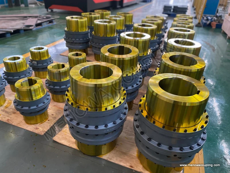
With the continuous development of modern industrial machinery towards large-scale, high-power and heavy-duty development, the application scope of gear type coupling in various industrial fields is becoming more and more extensive, and it has become an indispensable core connecting component in many key mechanical equipment. In the metallurgical industry, various rolling equipment, smelting auxiliary transmission equipment and metal processing heavy machinery need to bear high torque and continuous heavy load operation, and gear type coupling is used to connect the power shaft and transmission shaft of these equipment, ensuring the stable transmission of power in the high-load production process and adapting to the shaft misalignment caused by thermal deformation of metallurgical equipment during high-temperature operation. In the mineral mining industry, mining hoisting equipment, crushing machinery and ore conveying machinery have harsh operating environments, heavy working loads and frequent start-stop impacts, and gear type coupling relies on its high torque bearing capacity and reliable structural stability to adapt to the complex working conditions of mining sites and ensure the safe and stable operation of mining mechanical transmission systems. In the field of marine power propulsion, the power transmission system of marine ships needs to adapt to the vibration and displacement caused by ship navigation and wave impact, and gear type coupling can well compensate for the shaft misalignment of marine power equipment and maintain the efficient transmission of propulsion power. In heavy engineering machinery such as large cranes and excavators, the lifting and walking transmission mechanism needs to bear variable impact load and complex shaft displacement, and gear type coupling provides stable power transmission guarantee for the operation of engineering machinery. In addition, in industrial production conveying equipment, chemical heavy-duty machinery, thermal power generation auxiliary equipment and other fields, gear type coupling also plays an important role, providing reliable shaft connection and power transmission support for various heavy-duty mechanical systems.
Looking at the overall development and application of gear type coupling in the mechanical transmission industry, its unique structural design and excellent comprehensive performance determine its irreplaceable position in heavy-duty high-power transmission scenarios. Although with the continuous progress of mechanical technology, various new types of coupling products are constantly emerging, gear type coupling still maintains strong application vitality by virtue of mature manufacturing technology, stable transmission performance and wide working condition adaptability. In the future, with the continuous upgrading of industrial equipment and the improvement of mechanical operation requirements, gear type coupling will also be continuously optimized and improved in material selection, tooth profile design, sealing structure and lubrication technology, further improving its misalignment compensation capacity, wear resistance and service life, adapting to more complex and harsh industrial working conditions. For mechanical design and operation and maintenance management, attaching importance to the reasonable selection, standardized installation, scientific maintenance and timely fault handling of gear type coupling is not only to ensure the efficient and stable operation of a single transmission component, but also to lay a solid foundation for the long-term stable and safe operation of the entire mechanical equipment production system, reduce equipment operation failure rates and comprehensive maintenance costs, and create better operational benefits for industrial production and mechanical engineering applications.
https://www.menowacoupling.com/industrial-coupling/gear-type-coupling.html
Products
Tags
Related Articles
Gear Type Coupling Vendor In China
May 6, 2026In the global mechanical transmission industry, gear type couplings play an indispensable role as key components that connect rotating shafts, transmit torque, and compensate for axial, radial, and angular displacements between shafts. As one of the world’s major manufacturing hubs, China has nurtured a large number of…Diagram of Gear Type Coupling
Apr 29, 2026A gear type coupling is a crucial mechanical component widely utilized in industrial transmission systems to connect two rotating shafts, enabling the efficient transfer of torque while accommodating minor misalignments that may occur during operation. Unlike rigid couplings that require precise alignment between shafts…Gear Type Coupling Production
Apr 27, 2026Gear type couplings are essential mechanical components widely used in various industrial fields to connect two shafts and transmit torque while accommodating minor misalignments. The production of gear type couplings is a complex and precise process that requires strict control over every link, from material selection …Gear Type Coupling For Sale
Apr 27, 2026A gear type coupling is a versatile and robust mechanical device designed to connect two rotating shafts, enabling the efficient transmission of torque while accommodating a certain degree of misalignment between the shafts. This type of coupling is widely recognized for its ability to handle heavy loads and harsh opera…Working Principle of Gear Type Coupling
Apr 27, 2026A gear type coupling is a mechanical device specifically designed to connect two rotating shafts, enabling the efficient transmission of torque and rotational motion while accommodating a certain degree of misalignment between the shafts. Unlike rigid couplings that require precise alignment to function properly, gear t…Size Chart of Gear Type Coupling
Apr 27, 2026A size chart of gear type coupling is an indispensable reference tool in industrial power transmission systems, serving as a bridge between the functional requirements of machinery and the technical specifications of the coupling itself. It systematically organizes key dimensional and performance parameters, allowing en…
 WeChat
 WhatsApp