Cardan Joint Coupling
In the entire field of mechanical power transmission, the stable and efficient transfer of torque and rotational motion between different rotating shafts is the fundamental guarantee for the normal operation of all mechanical equipment systems. In actual mechanical installation and operation scenarios, it is almost impossible to keep all driving shafts and driven shafts in a completely coaxial and linear state for a long time. Various objective factors such as equipment installation deviation, structural deformation caused by long-term load operation, thermal expansion and contraction of metal components during working cycles, and subtle displacement generated by mechanical vibration will lead to different degrees of angular, radial and axial misalignment between connected shafts. Under such complex operating conditions, ordinary rigid coupling structures cannot adapt to the offset changes between shafts, and long-term forced operation will cause excessive additional load on the transmission system, accelerate the wear of shaft parts and bearing components, induce mechanical vibration and noise, and even lead to fatigue fracture of key transmission components and sudden shutdown of the entire equipment. The cardan joint coupling, as a classic flexible transmission connecting component with a long application history and mature mechanical principles, has become an indispensable core part of various mechanical transmission systems relying on its unique structural design, excellent angular misalignment compensation ability and stable torque transmission performance. It can effectively connect two shafts with intersecting axes or variable angular positions, continuously and stably transmit rotational power and torque, and well adapt to various dynamic and static offset changes generated during equipment operation, ensuring the continuity and stability of mechanical power output under complex working conditions.
The origin and development of the cardan joint coupling can be traced back to the early mechanical research and exploration stage, and the relevant mechanical structure design ideas were initially explored and sorted out by ancient mechanical researchers in the process of studying motion conversion and power transmission mechanisms. After continuous structural optimization and performance improvement by generations of mechanical engineers and technicians, this coupling structure has gradually evolved from the original simple gimbal mechanism to a standardized, serialized and refined mechanical transmission component widely used in modern industry and transportation fields. Different from other common flexible couplings that mainly rely on elastic deformation of elastic elements to compensate for shaft misalignment, the cardan joint coupling realizes flexible connection and motion transmission through the mutual rotation and hinge coordination of rigid mechanical components. Its core transmission logic does not depend on the elastic fatigue deformation of materials, but relies on the precise mechanical fit and relative rotational movement between metal structural parts, which makes it have outstanding advantages in bearing large torque, adapting to large angular deflection and maintaining long-term structural stability. Whether in light-duty small mechanical transmission occasions or heavy-duty heavy industrial equipment power connection scenarios, the cardan joint coupling can adjust its structural specifications and component matching according to actual working condition requirements, and always maintain reliable transmission performance, showing strong adaptability and practicality that many other types of couplings cannot match.
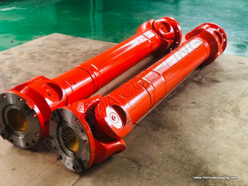
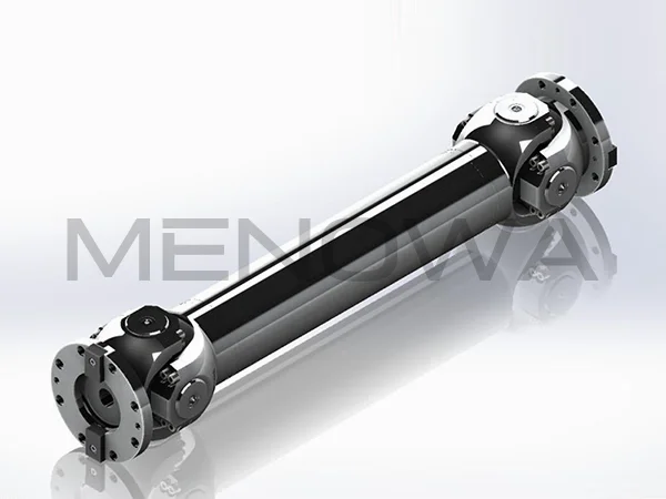
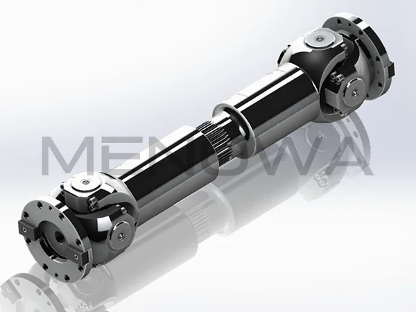
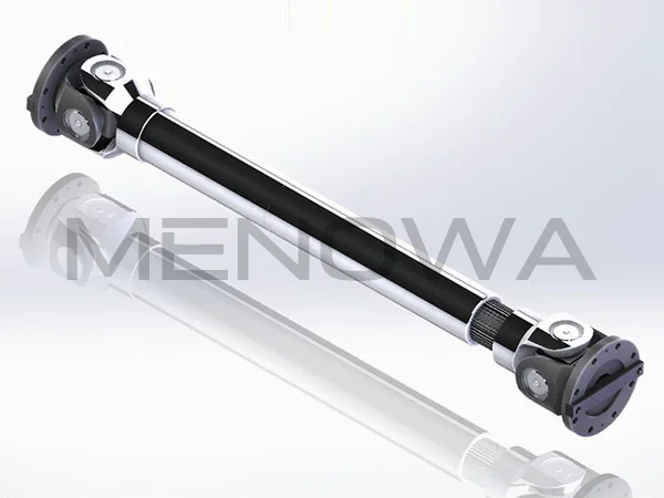
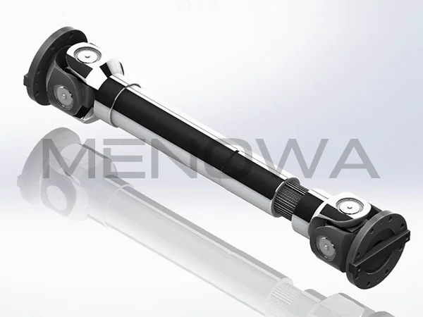
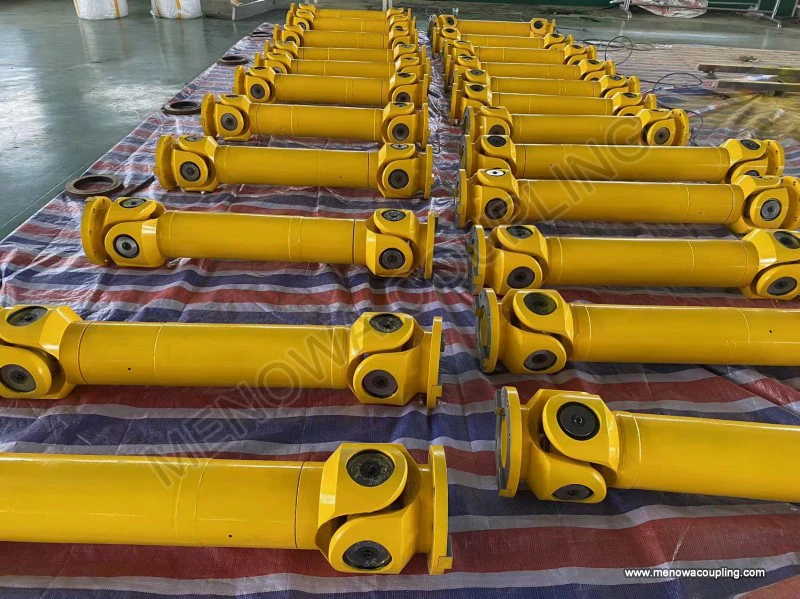
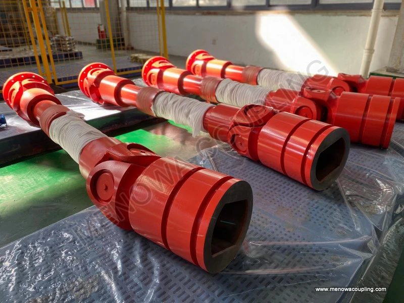
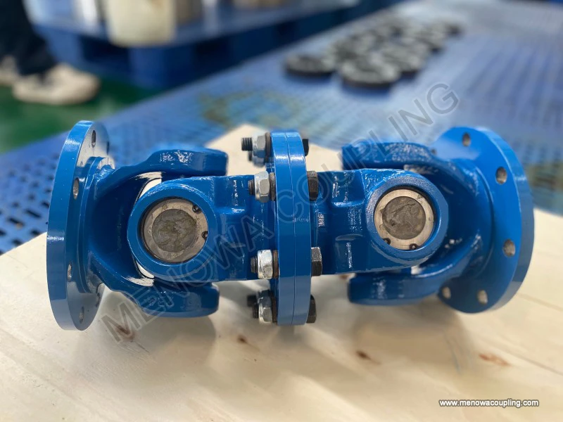
The basic structural composition of the cardan joint coupling is simple and rigorous, and all core components cooperate with each other in a coordinated manner to jointly complete the dual core functions of torque transmission and misalignment compensation. The most basic single cardan joint coupling assembly is mainly composed of two joint yokes, a cross-shaped intermediate connecting part often called cross spider, and a set of rotating auxiliary bearing components matched with each connecting end of the cross spider. Each component has a clear division of labor and bears different mechanical loads and motion functions in the transmission process. The two joint yokes are the connecting bases for the coupling to connect the driving shaft and the driven shaft respectively. One end of each yoke is designed with a shaft hole structure for fixed assembly with the shaft body, and the other end is processed into a fork-shaped open structure, which is used for hinged assembly with the cross spider. The cross spider is the central force-bearing and motion conversion core component of the entire cardan joint coupling. It presents a symmetrical cross spatial structure, with four cylindrical trunnions extending outward in two mutually perpendicular directions. The geometric center points of all trunnion rotation axes intersect at the same spatial point, which is the key structural basis for the coupling to realize angular deflection and rotational motion transmission. The bearing components installed between the trunnions of the cross spider and the inner wall of the fork-shaped structure of the joint yoke are mostly precision needle roller bearings, which can effectively reduce the friction resistance during the relative rotation between the cross spider and the joint yoke, avoid dry friction and excessive wear between metal rigid parts, and ensure the flexibility and smoothness of the coupling during angle adjustment and rotation operation. All structural components are made of high-strength alloy steel materials through forging and precision machining, with high structural rigidity, good fatigue resistance and strong impact load resistance, which can withstand the alternating torque and instantaneous impact load generated during long-term continuous operation of the mechanical equipment.
The internal assembly relationship of the cardan joint coupling follows strict geometric mechanical design standards. The four trunnions of the cross spider are respectively inserted into the bearing installation holes of the two fork-shaped joint yokes, and the two groups of mutually perpendicular hinge rotation pairs are formed through the matching of needle roller bearings. One group of hinge rotation pairs can realize the relative rotation and angle adjustment of the joint yoke around one spatial axis, and the other group of hinge rotation pairs can realize the relative rotation and angle adjustment around the other spatial axis perpendicular to the former. The cooperative work of the two groups of rotation pairs enables the entire coupling to freely adjust the angular position between the driving shaft and the driven shaft within a certain allowable angle range. In the actual assembly process, the fit clearance between the bearing components and the trunnions, as well as the assembly tightness between the joint yokes and the shaft body, need to be precisely controlled. Excessive fit clearance will cause vibration and impact during rotation, increase additional dynamic load, and too small clearance will lead to poor rotation flexibility, increased friction heat generation, and accelerated component wear. After the assembly of all components is completed, the overall structural stability of the coupling can be maintained. When the driving shaft rotates, the torque and rotational motion will be transmitted to the cross spider through one joint yoke, and then the cross spider will transmit the power to the other joint yoke through the hinge rotation pair, so as to drive the driven shaft to rotate synchronously, realizing the continuous transmission of mechanical power between the two shafts with angular misalignment.
The working mechanism of the cardan joint coupling follows the basic laws of spatial kinematics and mechanical torque transmission, and its core operating principle is based on the structural characteristics of the cross hinge to realize motion transmission under the condition of shaft axis intersection and angular deflection. When the driving shaft and the driven shaft are in a completely coaxial linear state without any angular deviation, the rotation speed of the driving shaft and the driven shaft remains completely synchronized, and the torque transmission process is stable and uniform without any speed fluctuation and additional dynamic load. However, in most actual working conditions, there is a certain included angle between the driving shaft and the driven shaft, which is the typical working state of the cardan joint coupling. Under the condition of angular deflection, the single cardan joint coupling will present a unique kinematic characteristic in the rotation process, that is, the instantaneous rotation speed of the driven shaft will have periodic fluctuation changes relative to the driving shaft within a single rotation cycle. This speed fluctuation is an inherent kinematic characteristic determined by the geometric structure of the single cardan joint, not caused by structural wear or assembly failure. The specific change rule is that when the trunnion of the cross spider rotates to different angular positions, the effective transmission radius of rotational motion changes periodically, resulting in the acceleration and deceleration alternate rotation of the driven shaft in each rotation cycle.
The magnitude of the speed fluctuation of the single cardan joint coupling is directly related to the size of the angular deflection between the driving shaft and the driven shaft. The smaller the included angle between the two shafts, the smaller the amplitude of the instantaneous speed fluctuation of the driven shaft, the more stable the overall transmission process, and the smaller the additional dynamic load generated by the speed change. With the gradual increase of the angular deflection between the two shafts, the amplitude of the instantaneous speed fluctuation increases correspondingly, the periodic impact and vibration of the transmission system become more obvious, and the additional alternating load borne by the coupling components and the connected shaft parts also increases accordingly. Although there is periodic speed fluctuation in the operation of the single cardan joint coupling, its average rotation speed of the driving shaft and the driven shaft remains consistent in each complete rotation cycle, which ensures the overall continuity and stability of mechanical power transmission. For many mechanical equipment that do not have extremely high requirements for instantaneous rotation speed stability and only need to ensure stable average power transmission, the single cardan joint coupling can fully meet the actual use needs, and its inherent speed fluctuation will not have a negative impact on the normal operation and working efficiency of the equipment.
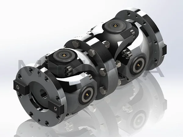
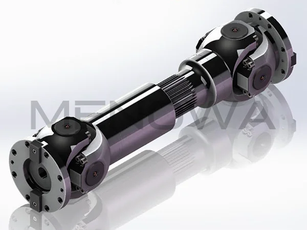
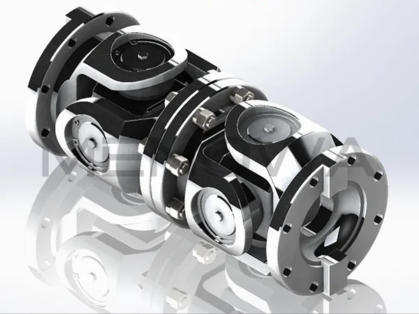
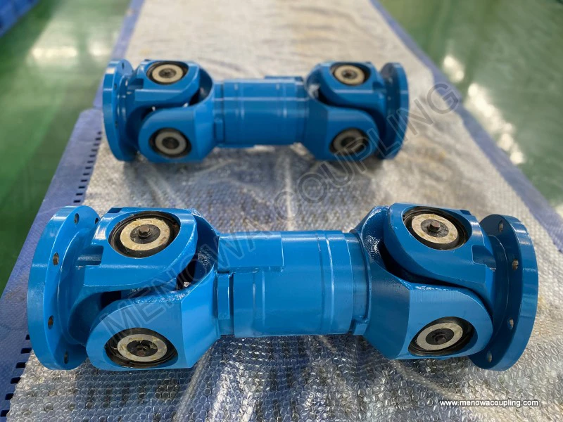
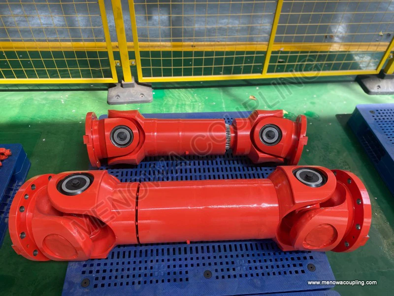
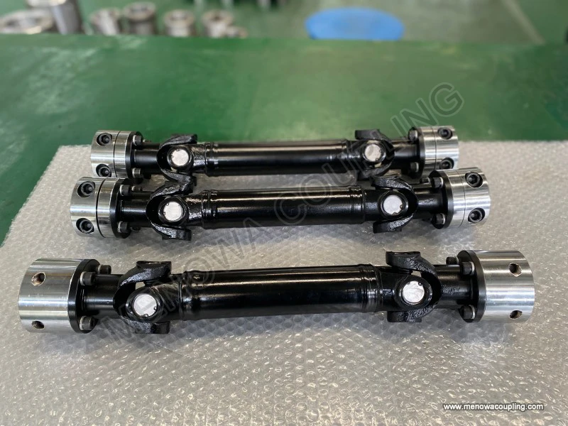
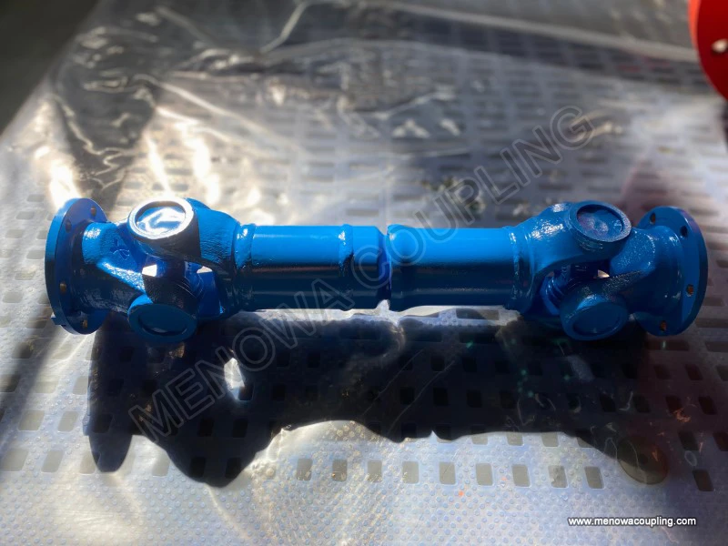
To solve the problem of instantaneous speed fluctuation of the single cardan joint coupling under angular deflection working conditions, the double cardan joint coupling structure has been developed and widely applied on the basis of the single structure. The double cardan joint coupling is formed by connecting two single cardan joints in series through a short intermediate connecting shaft or integrated fork structure, and the two single cardan joints are installed and arranged according to specific angular phase matching requirements. Through the complementary kinematic effect of the two single cardan joints, the speed fluctuation generated by the former single joint in the rotation process can be completely offset by the latter single joint, so that the instantaneous rotation speed of the final driven shaft remains consistent with the driving shaft at all times, realizing constant velocity power transmission. This structural improvement design retains all the advantages of the single cardan joint coupling in angular misalignment compensation and torque transmission, and effectively makes up for the defect of periodic speed fluctuation of the single structure, making the double cardan joint coupling suitable for mechanical transmission occasions with high requirements for rotation speed stability, smooth operation and low vibration and noise. The design and application of the double cardan joint coupling further expand the application scope of the cardan joint coupling series structures, enabling them to adapt to more precise and high-standard mechanical working conditions.
In terms of comprehensive operational performance, the cardan joint coupling has many remarkable inherent advantages compared with other traditional coupling products. First of all, it has excellent large angular misalignment compensation capability, and can normally work and stably transmit torque under the working condition that the included angle between the driving shaft and the driven shaft reaches a relatively large range. This compensation performance is far superior to rigid couplings and ordinary elastic couplings with small deformation allowance, and can well adapt to various installation deviations and dynamic displacement changes generated during equipment operation. Secondly, the main force-bearing components of the cardan joint coupling are all rigid metal structural parts, which have high structural strength and rigidity, can bear large torque load and instantaneous impact load, and are not easy to deform and damage under heavy-duty working conditions, with strong bearing capacity and long service life. Thirdly, the overall structure of the coupling is compact and reasonable in layout, does not occupy too much installation space, and is convenient for installation, disassembly and maintenance. It can be applied to various mechanical equipment with compact internal structural space and complex installation environment. In addition, the transmission efficiency of the cardan joint coupling is high, the friction loss generated in the power transmission process is small, and most of the mechanical power input by the driving shaft can be efficiently transmitted to the driven shaft, which is conducive to reducing the energy consumption of mechanical equipment operation and improving the overall working efficiency of the system.
At the same time, the cardan joint coupling also has some inherent performance limitations that need to be reasonably paid attention to in the process of type selection and use. The most prominent limitation is the periodic instantaneous speed fluctuation and the corresponding additional dynamic load generated by the single cardan joint structure during operation. Although this problem can be solved by the double cardan joint structure, the double structure will increase the overall structural length and manufacturing and assembly cost of the coupling to a certain extent. In addition, due to the need for relative rotational friction between the internal hinge components of the cardan joint coupling, regular lubrication maintenance is required in the process of use. If the lubrication state is poor for a long time, the friction and wear of internal bearings and hinge parts will be accelerated, resulting in increased vibration and noise, reduced transmission accuracy, and even early failure of the coupling. Moreover, the cardan joint coupling is not suitable for ultra-high speed rotating working conditions. Under long-term ultra-high speed operation, the periodic dynamic load and centrifugal force generated by rotation will cause excessive temperature rise and structural fatigue of components, affecting the operational stability and service life of the coupling. Therefore, in the actual type selection application, it is necessary to reasonably select the single or double cardan joint structure according to the actual working condition requirements such as equipment rotation speed, angular deflection size, torque load and operation stability standards, and make scientific matching and installation debugging.
The application fields of cardan joint couplings cover almost all mainstream mechanical transmission industries, showing extremely strong industry adaptability and practical application value. In the field of road transportation machinery, cardan joint couplings are widely used in the transmission systems of various vehicles and engineering transportation equipment. In the vehicle power transmission mechanism, the power output by the engine needs to be transmitted to the rear drive axle through the transmission shaft. Due to the influence of vehicle body vibration, chassis suspension jitter and load change during driving, the relative position and angle between the engine output shaft and the drive axle input shaft will change dynamically in real time. The cardan joint coupling can well adapt to this dynamic angular misalignment change, stably transmit power, and ensure the normal driving power output of the vehicle. In various construction engineering machinery such as excavators, loaders and cranes, many working mechanisms need to transmit power between shafts with large angle deflection and frequent position changes. The cardan joint coupling relies on its large angular compensation capacity and heavy load-bearing performance to provide reliable power transmission guarantee for the rotation and lifting actions of engineering machinery working parts, and adapt to the harsh working environment of frequent impact and complex load of engineering equipment.
In the field of industrial production and processing machinery, cardan joint couplings are widely used in various production line transmission equipment, metallurgical machinery, mining machinery, chemical machinery and large fan and pump equipment. In the metallurgical industry, the rolling mill equipment needs to transmit large torque to complete the rolling processing of metal materials. The rolling mill will generate certain structural deformation and shaft position offset under the action of long-term high load rolling force. The cardan joint coupling can stably transmit large torque while compensating for shaft misalignment, ensuring the continuous and stable operation of the rolling production process. In the mining industry, underground mining machinery and conveying equipment often work in harsh environments such as dust, humidity and complex terrain. The cardan joint coupling has firm structural performance and strong environmental adaptability, is not easy to be damaged by external environmental interference, and can reliably complete power transmission work under long-term heavy-load and harsh working conditions. In various automated production line transmission systems, many transmission shafts need to be arranged in a staggered and angular manner due to the limitation of production line layout. The cardan joint coupling can realize flexible connection and power transmission between staggered shafts, meet the layout and operation requirements of automated production lines, and ensure the continuity and efficiency of industrial production and processing.
In the field of agricultural machinery and special mechanical equipment, the application of cardan joint couplings is also very common. Various agricultural machinery such as tractors, harvesters and tillers often work in complex field terrain. The working environment is bumpy and the load changes randomly. The power transmission shaft of agricultural machinery often produces large angular deflection and position displacement. The cardan joint coupling has simple structure, low maintenance cost and strong impact resistance, which is very suitable for the power transmission needs of agricultural machinery under variable load and complex terrain conditions. In some special mechanical equipment such as ship auxiliary transmission mechanisms and aerospace ground support equipment, cardan joint couplings are also used to realize power transmission between non-coaxial shafts, relying on their stable transmission performance and high structural reliability to ensure the normal operation of special equipment.
The structural design and performance optimization of cardan joint couplings have been continuously updated and improved with the development of modern mechanical manufacturing technology and mechanical design theory. With the continuous improvement of industrial equipment requirements for transmission efficiency, operation stability and service life of couplings, mechanical design technicians have carried out in-depth optimization and upgrading of the material selection, structural design and processing technology of cardan joint couplings. In terms of material selection, on the basis of traditional high-strength alloy steel, new wear-resistant and fatigue-resistant alloy materials are gradually adopted, and surface heat treatment processes such as quenching and tempering and surface carburizing and quenching are carried out on the surface of key components such as cross spiders and trunnions. This treatment can significantly improve the surface hardness and wear resistance of components, enhance the internal structural toughness and fatigue resistance, effectively delay the wear and fatigue aging speed of components, and further extend the overall service life of the coupling.
In terms of structural optimization design, through modern computer simulation technology and finite element analysis method, the stress distribution and deformation law of each component of the cardan joint coupling under different torque loads and angular deflection working conditions are accurately calculated and analyzed. The structural size and shape of the joint yoke, cross spider and other key components are optimized and adjusted, the stress concentration area inside the structure is reduced, the force uniformity of each component is improved, and the structural bearing capacity and impact resistance are further enhanced. At the same time, aiming at the problem of lubrication and wear of internal hinge parts, the optimized lubrication channel structure and sealing protection structure are designed. The improved lubrication structure can make the lubricating grease evenly cover all friction moving pairs, reduce friction and wear to the greatest extent. The enhanced sealing structure can effectively prevent external dust, impurities and moisture from entering the inside of the coupling, avoid lubricating grease deterioration and component corrosion, and maintain the good working state of the coupling for a long time.
The daily maintenance and scientific use management of cardan joint couplings are key links to ensure their long-term stable operation and give full play to their transmission performance. Although the overall structural reliability of cardan joint couplings is high, long-term continuous operation under variable load, impact and angular deflection working conditions will inevitably lead to normal wear and aging of internal components. Scientific and standardized maintenance work can effectively reduce the failure probability of couplings, extend service life, and avoid mechanical equipment shutdown and production loss caused by coupling failure. The core content of daily maintenance work is regular lubrication maintenance. According to different working load and operation frequency, regular lubricating grease replacement and lubrication supplement should be carried out for the hinge rotating pairs and bearing components inside the coupling. Good lubrication conditions can reduce metal friction and wear, reduce vibration and noise, and avoid high temperature ablation of components caused by dry friction.
In addition to lubrication maintenance, regular visual inspection and disassembly inspection of the cardan joint coupling are also required. In the daily inspection process, it is necessary to observe whether the coupling has abnormal vibration, abnormal noise, oil leakage and other abnormal phenomena during operation. Check whether the connecting parts between the coupling and the shaft body are loose, whether the surface of the coupling components has obvious deformation, crack and wear damage. If any abnormal situation is found, timely shutdown inspection and maintenance should be carried out to avoid small faults evolving into large mechanical failures. For the couplings that have been used for a long time, regular disassembly and maintenance should be carried out to check the wear degree of internal needle roller bearings, cross spider trunnions and hinge matching surfaces, replace severely worn and aging components in time, and reassemble and debug the coupling to ensure that its assembly accuracy and transmission performance meet the working requirements. At the same time, in the operation process of mechanical equipment, avoid long-term overload operation and sudden frequent start-stop impact on the equipment, which can reduce the additional load and impact damage borne by the cardan joint coupling, and maintain its long-term stable and efficient working state.
Looking at the overall development trend of mechanical transmission components, with the continuous progress of intelligent manufacturing technology and the continuous upgrading of industrial equipment transmission performance requirements, the cardan joint coupling, as a classic basic mechanical component, will also continue to develop and innovate in the direction of higher transmission efficiency, stronger load-bearing capacity, longer service life and more intelligent maintenance management. In the future, with the application of new materials, new processing technologies and intelligent monitoring technologies, the structural performance of cardan joint couplings will be further improved, the application scope will be further expanded, and they will continue to play an irreplaceable core role in various mechanical transmission fields. Whether in traditional industrial production, transportation and agricultural machinery fields, or in emerging intelligent equipment and special mechanical fields, cardan joint couplings will always rely on their mature mechanical principles reliable structural performance and strong working adaptability to provide solid basic guarantee for the stable operation and efficient power transmission of various mechanical equipment systems.
https://www.menowacoupling.com/industrial-coupling/cardan-joint-coupling.html
 WeChat
 WhatsApp