Rigid Coupling
In the complex and interconnected ecosystem of modern mechanical transmission systems, every small mechanical component undertakes an irreplaceable basic responsibility for the stable operation, power transmission efficiency and running accuracy of the entire equipment. Among numerous transmission connection parts, rigid coupling stands out as a foundational connecting element that focuses on rigid locking and synchronous power transmission between rotating shafts, serving as a critical bridge linking driving components and driven components in all kinds of industrial mechanical equipment. Unlike other flexible connecting parts that are designed to buffer vibration and compensate for shaft misalignment, rigid coupling adheres to the design concept of integrated rigid connection from structural conception to practical application, realizing the integrated rotation of two connected shafts without relative displacement, angular deviation or elastic deformation during the entire power transmission process. This inherent design characteristic makes rigid coupling an essential component in mechanical scenarios that pursue high transmission synchronization, stable torque output and long-term consistent running precision, and it has been widely applied in heavy industrial manufacturing, precision mechanical processing, fluid power transmission, energy power operation and many other core industrial fields. Understanding the internal working logic, structural design characteristics, material matching rules, assembly key points, daily maintenance norms and application adaptation principles of rigid coupling is not only a necessary professional literacy for mechanical design engineers and equipment maintenance technicians, but also an important prerequisite for ensuring the long-term stable and efficient operation of mechanical transmission equipment, reducing unnecessary mechanical wear and extending the overall service life of mechanical units.
The essential working logic of rigid coupling is built on the basis of physical rigid locking and direct torque transmission, and its core operating principle is straightforward and practical, without complex elastic energy storage structure or dynamic buffer mechanism inside the whole component. In the actual assembly and working state, the rigid coupling is firmly installed and fixed on the shaft ends of the driving equipment and the driven equipment respectively, and the two separate coupling parts are closely connected and locked through fasteners such as bolts, set screws or key connecting structures, forming an integrated whole between the driving shaft, the coupling itself and the driven shaft. When the driving device starts to operate and generate rotational power and torque, the rotational force and torque generated by the driving shaft will be directly transmitted to the coupling connected to the shaft end through the fixed connecting structure, and the rigid integrated structure of the coupling will completely transfer all the received torque and rotational power to the other half of the coupling and the connected driven shaft in real time. In this whole transmission process, there is no elastic deformation, sliding friction, relative rotation or displacement compensation between any connecting parts of the rigid coupling, and the two connected shafts always maintain a completely synchronous rotating state with consistent speed, consistent rotation angle and no phase difference. This direct and unbuffered torque transmission mode enables the rigid coupling to maintain stable power transmission efficiency under various load conditions, and avoids power loss and transmission delay caused by elastic deformation or structural buffering in the transmission process. It is important to note that the working performance and service life of rigid coupling are highly dependent on the installation alignment accuracy of the two connected shafts. Due to the lack of any structural design to compensate for shaft misalignment, angular deviation or axial displacement, any slight parallel misalignment, angular deflection or axial gap between the driving shaft and the driven shaft will be directly converted into additional mechanical stress and alternating load on the coupling and the shaft body during operation. These extra loads will not only accelerate the wear of the coupling connecting parts and the shaft surface, but also cause vibration and noise during equipment operation, and even lead to fatigue damage of the shaft body and premature failure of the coupling in severe cases, which is why precise shaft alignment is always the primary prerequisite for the normal and reliable use of all types of rigid coupling products.
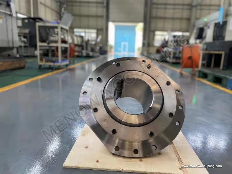
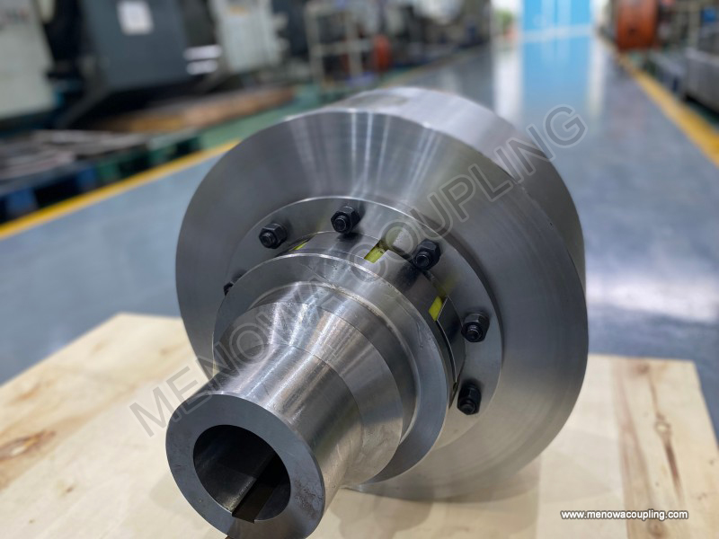
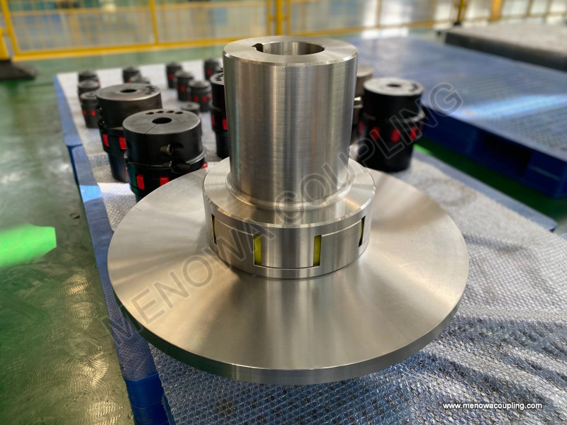
The structural design of rigid coupling follows the core design idea of simplification, firmness and high rigidity, and the overall structural composition is concise without redundant auxiliary parts or complex movable matching structures, which also determines its characteristics of convenient processing and manufacturing, simple assembly and disassembly, and low daily maintenance difficulty in practical application. All rigid couplings on the market are composed of two symmetrical or semi-symmetric rigid main bodies and supporting connecting and fixing parts, and there is no flexible medium, elastic element, sliding part or rotating buffer structure inside the whole product. According to the differences in structural form, processing technology and assembly and disassembly methods, rigid couplings can be divided into several common structural types, each with unique structural characteristics and applicable working condition scenarios, adapting to different shaft diameter specifications, torque transmission requirements and equipment installation space conditions. The first common type is the sleeve rigid coupling, also known as the muff coupling, which adopts an integrated cylindrical sleeve structure as the main body, the inner hole of the sleeve matches the outer diameter of the two connected shafts, and the fixation between the sleeve and the shaft is realized through key connection or set screw locking. This structural design is extremely compact in overall size, occupies little installation space, has a simple processing and forming process, and the overall rigidity of the cylindrical sleeve structure is uniform and stable. It is suitable for light and medium load transmission scenarios with small shaft diameter, low rotating speed and stable equipment operation load, and is often used in small mechanical transmission equipment and conventional general mechanical supporting facilities. The second widely used type is the split rigid coupling, also called the clamp rigid coupling, which divides the integral coupling main body into two symmetrical semicircular clamp structures, and the two semicircular clamps are locked and fixed by high-strength bolts after being sleeved on the shaft ends. The biggest structural advantage of this type of coupling is that it does not need to move the axial position of the equipment during installation and disassembly, the assembly and maintenance operation is very convenient, and the clamping force generated by bolt locking can make the coupling and the shaft form a tight fit without relative sliding. The split structure design also makes the stress distribution of the coupling more uniform during operation, and it can adapt to medium and heavy load transmission working conditions, and is widely used in industrial pumps, fans, conventional gear transmission equipment and other general industrial mechanical equipment. The third mainstream structural type is the flange rigid coupling, which is composed of two flange discs with integrated shaft sleeves, each flange disc is fixedly connected with the driving shaft and the driven shaft respectively, and the two flange discs are closely connected and locked by a number of high-strength bolts arranged in a circumferential array. The flange structure has excellent overall structural rigidity and strong torque bearing capacity, and can withstand large impact load and long-term continuous heavy load operation. It is the preferred rigid coupling type for heavy-duty mechanical equipment, large-scale power transmission devices and high-torque industrial production equipment. In addition to these three main types, there are also some special structural rigid couplings designed for special working conditions and equipment space limitations, such as short-size compact rigid couplings for precision micro-mechanical equipment and special-shaped connecting rigid couplings for non-standard shaft connection requirements, but the core structural design and working principle of these special types are consistent with conventional rigid couplings, and they all maintain the basic characteristics of rigid integrated connection and synchronous direct transmission.
Material selection is a core link that directly determines the mechanical performance, load-bearing capacity, wear resistance, corrosion resistance and overall service life of rigid coupling, and different application working conditions and transmission load requirements correspond to different matching material types. The material selection of rigid coupling always takes rigidity, strength, fatigue resistance and processing performance as the core evaluation indicators, and comprehensively considers the operating environment temperature, medium corrosion degree, load impact frequency and other on-site working condition factors to ensure that the selected material can maintain stable mechanical properties and structural integrity during long-term continuous operation. Cast iron is one of the most traditional and commonly used materials for manufacturing rigid couplings, with the advantages of low production cost, good casting forming performance, simple processing technology and good vibration damping performance in static state. Rigid couplings made of cast iron have stable overall rigidity, are not easy to deform under conventional steady load, and are suitable for general industrial transmission scenarios with light and medium load, low rotating speed, stable operation and no severe impact load. However, cast iron materials have relatively low tensile strength and poor fatigue resistance, and are prone to brittle fracture under frequent impact load, alternating load and high-speed operation conditions, so they are not suitable for heavy-duty, high-speed and high-impact mechanical transmission working conditions. Carbon steel is another widely used mainstream material for rigid coupling production, with higher tensile strength, better structural toughness, excellent fatigue resistance and impact resistance compared with cast iron. Carbon steel rigid couplings can maintain stable structural performance under medium and heavy load, high-speed operation and frequent load switching conditions, have strong resistance to mechanical fatigue and structural deformation, and can adapt to most conventional industrial heavy-load transmission scenarios. At the same time, carbon steel has good welding performance and mechanical processing performance, which can meet the processing and production requirements of various complex structural rigid couplings, and can also be subjected to surface strengthening treatment such as quenching and tempering to further improve surface hardness and wear resistance. For precision mechanical equipment and high-precision transmission scenarios that require high coupling precision and light weight, aluminum alloy materials are often used to manufacture rigid couplings. Aluminum alloy has the characteristics of light specific gravity, high structural rigidity per unit weight, good processing precision and corrosion resistance, and the rigid couplings made of it have small overall weight, low rotational inertia during operation, and will not cause additional load on the rotating shaft due to their own weight. This kind of coupling is very suitable for precision automation equipment, numerical control processing equipment, micro transmission machinery and other scenarios that require high transmission precision and low rotational inertia. In some special working environments with strong corrosion, high temperature, low temperature or long-term contact with chemical media, stainless steel materials need to be selected to manufacture rigid couplings. Stainless steel has excellent corrosion resistance, high and low temperature resistance and oxidation resistance, can maintain stable structural performance in harsh working environments, and avoid structural rust, corrosion and performance degradation of the coupling caused by environmental factors, ensuring the long-term stable operation of the equipment. In addition to the base body materials, the fasteners such as bolts and set screws matched with rigid couplings also need to select corresponding high-strength materials according to the load level, to ensure that the locking connection structure will not loosen or fail during long-term operation, and maintain the overall rigid connection state of the coupling.
The installation and alignment operation of rigid coupling is the key link to ensure its optimal working performance and long service life, and the standardized and accurate installation process can effectively avoid additional mechanical stress, equipment vibration and premature component failure caused by shaft misalignment. Before the formal installation of the rigid coupling, comprehensive preparation work needs to be completed first, including checking the dimensional matching degree between the coupling inner hole and the shaft outer diameter, cleaning the surface of the shaft end and the coupling inner hole to remove oil stains, rust and processing burrs, and checking whether the coupling main body and supporting fasteners have processing defects or structural damage. After the preparation work is completed, the two coupling parts are respectively sleeved on the shaft ends of the driving equipment and the driven equipment, and the initial position is adjusted to ensure that the coupling is installed at the correct axial position of the shaft body. The most critical step in the whole installation process is the precise alignment of the two shafts, including parallel alignment and angular alignment. Parallel alignment ensures that the two connected shafts are on the same central axis in the horizontal and vertical directions, and angular alignment ensures that there is no angular deflection between the two shafts during rotation. In the actual alignment operation, professional measuring tools can be used to detect the runout deviation and displacement deviation of the shaft ends and the coupling end faces, and the position of the driven equipment is fine-tuned according to the detection data until the deviation value is controlled within the reasonable range specified by the mechanical design requirements. After the shaft alignment is completed, the fasteners of the rigid coupling are locked and tightened in a symmetrical and cross sequence, which can ensure that the locking force is evenly distributed on the whole coupling structure, avoid structural deformation and position deviation of the coupling caused by one-sided excessive locking force, and maintain the stable rigid connection state. After the installation and locking are completed, it is necessary to carry out a no-load test run of the equipment, observe whether there is abnormal vibration, noise and shaft runout during the operation, and recheck the alignment accuracy and fastening state of the coupling after the no-load operation for a period of time, and make fine adjustment if any deviation is found. Good installation and alignment work can make the rigid coupling give full play to the advantages of synchronous transmission and stable torque output, reduce the mechanical wear of the coupling and the shaft body, and lay a solid foundation for the long-term stable operation of the equipment.
Daily maintenance and regular inspection management of rigid coupling are important measures to extend its service life and maintain stable transmission performance. Although the structural design of rigid coupling is simple and durable, and there is no easily damaged vulnerable part, long-term continuous operation, load change, environmental impact and equipment vibration will still cause problems such as fastener loosening, surface wear and slight shaft position deviation, which affect the working effect of the coupling. The daily maintenance work of rigid coupling is relatively simple, mainly including keeping the coupling surface clean, avoiding long-term accumulation of dust, oil dirt and sundries on the surface, preventing sundries from affecting the rotating operation and causing local stress concentration. For the rigid couplings working in harsh environments such as high dust, high humidity and chemical corrosion, regular surface cleaning and anti-corrosion protection treatment should be done to avoid structural corrosion and material aging. The regular inspection work needs to be carried out periodically according to the equipment operation intensity and working environment conditions. The main inspection contents include checking the fastening state of all connecting bolts and set screws of the coupling to see if there is loosening, slipping or missing parts, checking the matching surface between the coupling and the shaft for wear, scratch and relative sliding marks, checking whether there is abnormal deformation, crack and structural damage on the coupling main body, and rechecking the alignment accuracy of the two connected shafts to see if there is position deviation caused by long-term operation and equipment vibration. Once loosened fasteners are found during the inspection, they should be tightened in time according to the standard locking torque; if slight wear is found on the matching surface, lubrication and protection treatment can be done properly; if structural cracks, serious wear and permanent deformation are found on the coupling main body, the coupling should be replaced in time to avoid equipment failure and production safety accidents caused by coupling failure. In addition, for the rigid couplings that work under frequent impact load and high-speed operation conditions, the inspection cycle should be appropriately shortened, and the fatigue damage detection of the coupling structure should be increased to ensure that potential hidden dangers can be found and eliminated in the initial stage. Scientific and standardized maintenance and inspection management can effectively reduce the failure probability of rigid coupling, maintain the stable transmission performance of the equipment, and reduce the maintenance cost and equipment downtime caused by coupling problems.
Rigid coupling has extremely wide application coverage in all fields of modern industrial production and mechanical manufacturing, and it plays an irreplaceable connecting and transmission role in various mechanical equipment that requires precise synchronization and stable power transmission. In the field of precision mechanical processing and automated production equipment, rigid couplings are used in numerical control machine tools, precision milling equipment, grinding machines and automated assembly lines. These processing and production equipment have extremely high requirements for rotating speed synchronization and position accuracy of the transmission shaft. Any transmission deviation and phase difference will directly affect the processing precision of parts and the assembly accuracy of products. The rigid connection and synchronous transmission characteristics of rigid couplings can ensure that the transmission shafts of the equipment maintain consistent rotation state, avoid transmission error caused by elastic deformation, and meet the high-precision production and processing requirements. In the field of fluid handling and industrial power transmission equipment, rigid couplings are widely matched with industrial water pumps, centrifugal fans, air compressors and gearbox transmission devices. These equipment need to transmit large torque for a long time under steady load conditions, and require high stability and reliability of the connecting parts. The high rigidity and high torque transmission capacity of rigid couplings can ensure stable power output of the equipment, avoid power transmission fluctuation caused by coupling deformation, and ensure the continuous and stable operation of fluid transportation and power transmission work. In the field of heavy industrial manufacturing and engineering machinery, rigid couplings are applied to large-scale transmission machinery, mining equipment and metallurgical production equipment. These equipment often work under heavy load and complex working conditions, and the connecting parts need to have strong structural strength and impact resistance. The flange rigid couplings and heavy-duty split rigid couplings with high structural rigidity can withstand long-term heavy load and occasional impact load, ensuring the reliable connection and power transmission of large mechanical equipment. In the field of new energy power generation and special mechanical equipment, rigid couplings are also used in generator sets, wind power auxiliary transmission equipment and environmental protection treatment equipment. These equipment require long-term uninterrupted operation and high equipment operation stability, and the simple structure and stable performance of rigid couplings can reduce the failure rate of transmission parts and ensure the long-term safe operation of power generation and environmental protection equipment. With the continuous upgrading of industrial manufacturing technology and the continuous improvement of equipment precision requirements, the application scope of rigid couplings is still expanding, and the matching design of rigid couplings is also constantly optimized according to the actual working condition needs of different industries.
With the continuous progress of mechanical design technology, material processing technology and industrial intelligent manufacturing level, the design and production of rigid coupling are also constantly developing and optimizing towards the direction of structural refinement, material high performance, processing precision and application specialization. In the early stage of rigid coupling development, the product design only focused on meeting the basic shaft connection and torque transmission functions, the structural design was relatively rough, the material selection was single, and the processing precision was low, which could only adapt to the simple and low-precision mechanical transmission scenarios in the early industrial stage. With the rapid development of modern industrial production, the requirements for equipment transmission precision, operation stability and service life are constantly improved, prompting the rigid coupling design to pay more attention to structural stress optimization, weight reduction design and precision matching processing. Modern rigid coupling design will use professional mechanical simulation software to carry out finite element stress analysis on the coupling structure, optimize the structural size and stress distribution of the coupling, avoid local stress concentration, improve the structural fatigue resistance and deformation resistance of the coupling, and realize the lightweight design of the product while ensuring high rigidity. In terms of material application, with the continuous emergence of new high-strength alloy materials and special anti-corrosion materials, rigid couplings can adapt to more harsh working environments and higher load transmission requirements, and the comprehensive mechanical performance of products is continuously improved. In terms of processing technology, the popularization and application of precision numerical control processing technology and fine surface treatment technology make the dimensional matching accuracy and surface finish of rigid couplings higher, the assembly matching effect better, and the transmission synchronization performance further improved. In terms of application matching, personalized and customized rigid coupling design has become a development trend. According to the special shaft diameter size, installation space, load characteristics and environmental conditions of different mechanical equipment, non-standard rigid coupling products are customized to meet the special connection needs of various special mechanical equipment. In the future, with the continuous advancement of industrial automation and intelligent production, rigid coupling, as the basic core connecting component of mechanical transmission systems, will continue to play an important role in the industrial field, and its technical design and production manufacturing will continue to iterate and progress with the development of modern mechanical engineering technology, providing more reliable and high-precision basic guarantee for the stable operation of all kinds of mechanical equipment.
Throughout the entire mechanical transmission system engineering, rigid coupling may seem to be a small and basic mechanical component, but it bears the key core function of connecting rotating shafts, transmitting torque and maintaining synchronous operation of equipment, and its performance quality, installation accuracy and maintenance management level are directly related to the overall operating efficiency, processing precision and service life of mechanical equipment. Different from flexible coupling products that focus on vibration buffering and misalignment compensation, rigid coupling relies on its inherent high-rigidity integrated structural design, realizes direct and efficient torque transmission without relative displacement and elastic deformation, and becomes an indispensable key component in all mechanical scenarios that pursue high synchronization, high precision and high stability transmission. From structural type division and scientific material selection, to standardized installation and precise alignment, and then to daily maintenance and regular inspection management, every link affects the final use effect and service life of rigid coupling. Only by deeply understanding the working principle and structural characteristics of rigid coupling, scientifically selecting appropriate product types and material specifications according to actual working conditions, strictly implementing standardized installation and alignment operations, and doing a good job in daily maintenance and regular inspection work, can we give full play to the excellent transmission performance of rigid coupling, ensure the long-term stable and efficient operation of mechanical transmission equipment, and create stable production benefits for all kinds of industrial production and mechanical processing work. In the continuous development of modern mechanical engineering and industrial manufacturing, rigid coupling will always maintain its important basic position in the mechanical transmission field, and continuously adapt to the changing industrial production needs through continuous design optimization and technological upgrading, and escort the stable operation and efficient development of various mechanical equipment.
https://www.menowacoupling.com/industrial-coupling/rigid-coupling.html
 WeChat
 WhatsApp