Structure of Universal Coupling
A universal coupling, widely recognized as a core mechanical transmission component in modern machinery systems, serves as a flexible connection device designed to transmit rotational torque and motion between two shafts that present angular, parallel, or axial misalignment. Its unique structural configuration enables stable power transmission under dynamic offset conditions, making it indispensable in general machinery, transportation equipment, and industrial transmission systems. Unlike rigid couplings that require precise shaft alignment, the structural design of universal couplings focuses on flexible deformation and adaptive movement, allowing continuous and efficient power output even when connected shafts produce real-time position changes during operation. The overall structural composition follows a mature mechanical logic, combining rigid load-bearing components and flexible movable structures to balance structural stability, motion flexibility, and torque transmission capacity, and all structural parts coordinate with each other to adapt to complex working conditions such as variable angles and alternating loads.
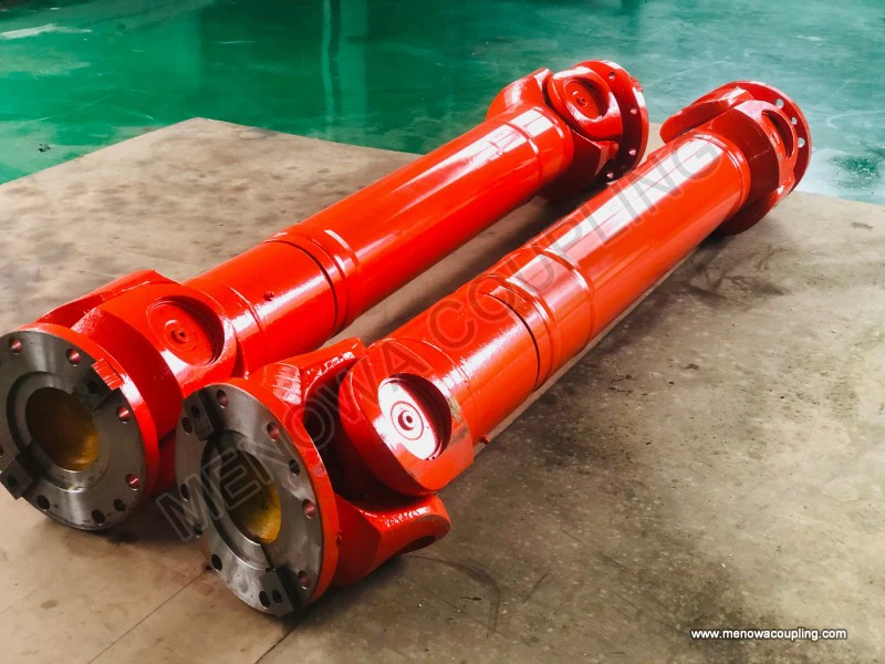
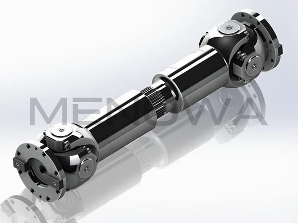
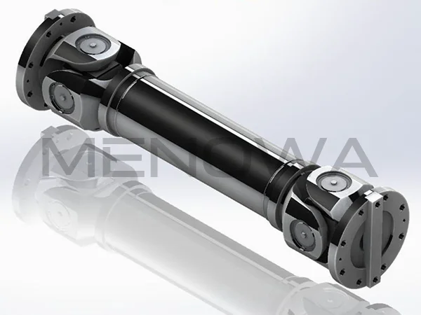
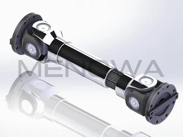
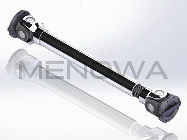
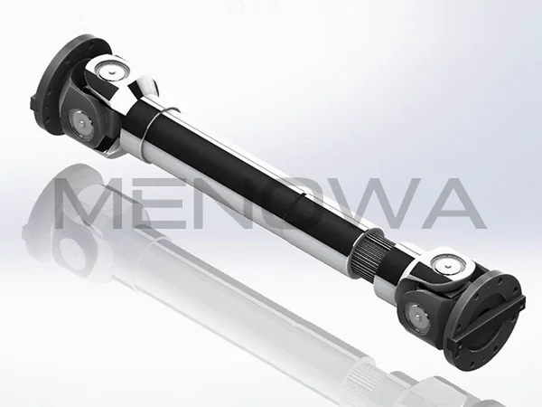
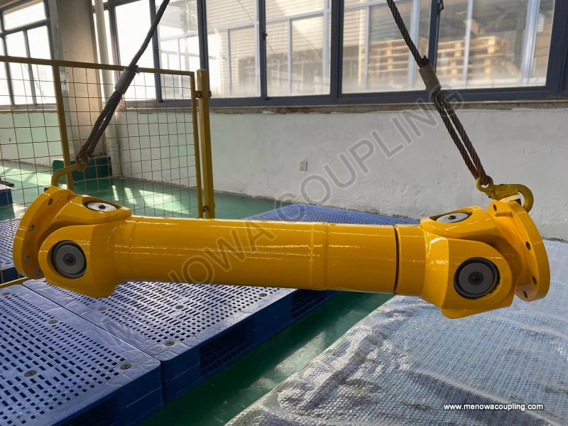
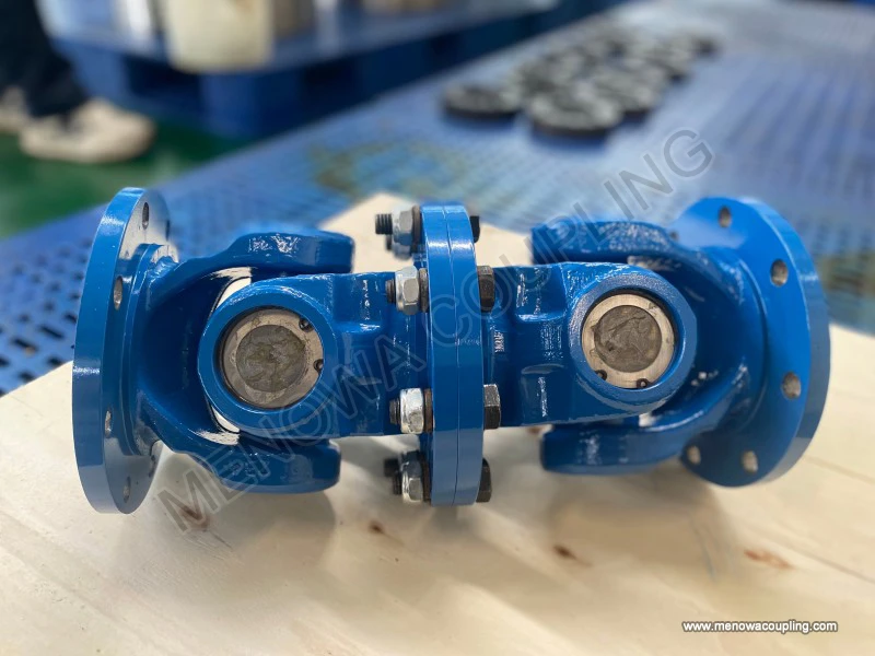
The basic overall structure of a standard single universal coupling is composed of three core functional units: dual yoke assemblies, a central cross shaft component, and auxiliary friction reducing and fastening components. These parts form a closed movable connection system, where the two yokes are respectively fixed to the driving shaft and driven shaft, and the cross shaft is clamped between the two yokes to realize the angular rotation connection between the shafts. The entire structure adopts a symmetric layout in spatial geometry, with the cross shaft’s four journal ends distributed perpendicularly, forming a 90-degree spatial included angle, which lays the structural foundation for multi-directional angular compensation. This classic structural form has been optimized and inherited in long-term engineering applications, and although there are differentiated structural designs for different load levels and usage scenarios, the core combination logic of yoke-cross shaft-yoke remains unchanged, ensuring the basic transmission performance of the universal coupling.
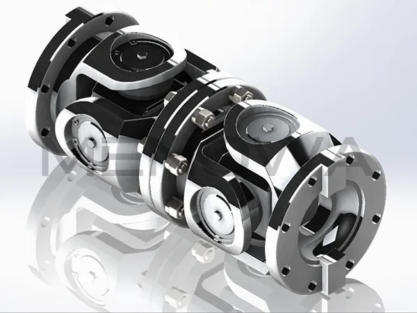
Yokes, also referred to as fork heads, are the main load-bearing and connecting structures of universal couplings, and their structural shape and dimensional accuracy directly determine the connection stability and load-bearing limit of the entire device. Each universal coupling is equipped with two independent yokes, classified as the driving-end yoke and the driven-end yoke according to their assembly positions. The overall structure of the yoke presents a fork-shaped design, with one end being a complete shaft sleeve structure for tight sleeving and fixing with the transmission shaft, and the other end split into two parallel ear plates with reserved assembly holes. The shaft sleeve part of the yoke is designed with a thickened wall structure, which can effectively disperse the concentrated torque and axial load generated during high-speed rotation, avoiding structural deformation or fracture caused by local stress concentration. The parallel ear plates at the fork end maintain high dimensional symmetry and flatness, ensuring that the assembly holes on the two ear plates are coaxial, which provides precise positioning conditions for the installation of the cross shaft journals.
In terms of structural details, the inner wall of the yoke shaft sleeve is usually processed with high-precision smooth surfaces to achieve close clearance fit with the outer circle of the transmission shaft, preventing relative sliding between the coupling and the shaft during torque transmission. Some yoke structures are designed with auxiliary fastening grooves or threaded holes on the outer wall of the shaft sleeve, which are used to install positioning fasteners to strengthen the connection tightness and avoid axial displacement of the coupling during long-term operation. The thickness of the yoke ear plates is strictly matched with the length of the cross shaft journals, which can limit the axial movement of the cross shaft while ensuring flexible rotation of the journals, preventing excessive clearance from causing vibration and impact during equipment operation. As the main force-bearing component, the yoke’s structural strength is optimized integrally, with smooth transition arcs set at the junction of the shaft sleeve and the fork ear plates to eliminate sharp corners, reduce stress concentration during alternating load operation, and extend the service life of the structure.
The cross shaft, also named the spider or trunnion, is the core motion conversion component of the universal coupling and the key structure to realize angular compensation transmission. Its overall structure is a one-piece cross-shaped symmetrical component, with four cylindrical journals extending perpendicularly from the central matrix, and the axes of every two opposite journals coincide strictly, forming two mutually perpendicular rotation axes in space. The central matrix of the cross shaft adopts a solid thickened structure, which has high rigidity and torsion resistance, and can bear large torque loads without torsional deformation. The four journal ends are processed with high-precision cylindrical surfaces, and the surface smoothness is strictly controlled to reduce friction resistance during relative rotation with the matching components.
The structural design of the cross shaft has distinct functional pertinence. The length and diameter of the journals are designed according to the load demand of the coupling: journals with larger diameters and shorter lengths are used for heavy-load working conditions to improve shear resistance and structural stability, while slender journals are adopted for light-load and high-speed scenarios to reduce rotational inertia and improve transmission flexibility. The transition position between the journal and the central matrix adopts a rounded arc transition structure, which avoids root fracture caused by stress concentration when the journal rotates at an angle and bears torque. In the overall assembly structure, two opposite journals of the cross shaft are embedded in the assembly holes of one yoke’s ear plates, and the other two journals are connected with the other yoke, realizing the mutual rotation of the two yokes around two perpendicular axes, thus enabling the coupling to adapt to the angular deflection of the connected shafts.
Bearing components are essential auxiliary structural parts of universal couplings, mainly installed at the matching positions of the cross shaft journals and yoke assembly holes, playing the roles of friction reduction, support and positioning. Most universal couplings adopt needle roller bearing structures, which are compact in size and high in bearing capacity, suitable for the narrow assembly space of coupling structures. The bearing structure consists of a bearing outer ring, dense needle rollers and a retaining frame. The bearing outer ring is tightly embedded in the reserved holes of the yoke ear plates, forming a fixed outer ring structure, while the inner side of the needle rollers is in contact with the outer circle of the cross shaft journals, realizing rolling friction during the rotation of the cross shaft relative to the yoke.
This embedded bearing structure effectively solves the problem of high friction and serious wear caused by direct contact and relative rotation between the cross shaft and the yoke. The dense arrangement of needle rollers can uniformly bear the radial load generated during torque transmission, avoiding local pressure overload. At the same time, the bearing structure is equipped with a closed limit design, which can prevent the needle rollers from falling off during high-speed rotation and angular movement, ensuring the stability of the transmission structure. Some improved structural designs add sealing gaskets at the outer end of the bearing assembly holes, forming a closed lubrication space inside the bearing, which can store lubricating grease, isolate external dust and impurities, and reduce structural wear and failure probability.
Fastening and sealing auxiliary structures constitute the complete assembly system of the universal coupling, ensuring the long-term stable operation of the main structural components. Common fastening structures include circlips, end covers and positioning pins. Circlips are installed at the outer ends of the yoke assembly holes, clamping the bearing outer ring to limit its axial displacement and prevent the bearing from loosening and falling off during equipment vibration and rotation. End cover structures are mostly used for medium and large-sized universal couplings, covering the outer side of the yoke assembly holes to further compress the bearing and sealing components, and improving the overall structural tightness. Positioning pins are arranged at the matching positions of the yoke shaft sleeve and the transmission shaft, penetrating through the reserved pin holes to realize circumferential positioning, preventing relative rotation between the coupling and the shaft and ensuring accurate transmission of torque.
The sealing structure is a key guarantee for the durable operation of the coupling structure. In addition to the bearing end sealing gaskets, the matching gaps between the yoke and the cross shaft journals are also equipped with elastic sealing rings. These sealing components can effectively lock the internal lubricating medium, maintain the lubrication state of the friction pairs for a long time, and prevent dry friction and abrasion failure. Meanwhile, they can block external moisture, dust and granular impurities from entering the internal movable gaps, avoiding abrasive wear of the cross shaft journals and bearings, and reducing the failure rate of the transmission structure. The elastic design of the sealing components can adapt to the small displacement and angular deformation of the coupling during operation, without affecting the flexible movement of the main structure.
According to the structural combination form, universal couplings can be divided into single-section and double-section structures, with obvious differences in structural characteristics and functional adaptation. The single-section universal coupling is the most basic structural form, composed of two yokes, one cross shaft and matching auxiliary parts, with a compact overall structure and small occupied space. Its structural limitation lies in the non-uniform speed transmission characteristic during large-angle operation, that is, the output shaft speed fluctuates periodically with the rotation of the input shaft, which is suitable for low-speed, medium and small torque transmission scenarios with low requirements for transmission stability.
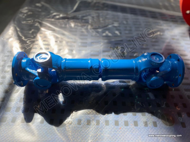
The double-section universal coupling optimizes the transmission performance through structural combination, which is composed of two groups of cross shaft structures and three yokes, with the middle yoke connecting the two cross shafts to form a linkage transmission structure. This combined structure compensates for the speed fluctuation defect of the single-section structure through the phase difference of the two groups of universal transmission units, realizing approximate constant-speed torque transmission. Structurally, the two groups of cross shaft mechanisms of the double-section coupling maintain parallel spatial posture, and their angular compensation ranges are superimposed, so the overall structure can adapt to larger shaft misalignment angles and more complex spatial position deviations. The structural design of the middle yoke focuses on balance and symmetry, with consistent assembly precision and structural strength at both ends, ensuring synchronous and stable operation of the two transmission units.
From the perspective of structural mechanical characteristics, all components of the universal coupling form a scientific force transmission path. Torque is first transmitted from the driving shaft to the driving-end yoke, then transferred to the cross shaft through the matching bearing structure, and finally transmitted to the driven-end yoke and the driven shaft through the other group of journal structures of the cross shaft. In this process, the cross shaft bears torsional load and radial alternating load, the yokes bear bending load and tensile and compressive load, and the bearings bear contact pressure and friction load. The differentiated structural strength design of each component matches its force-bearing characteristics, realizing reasonable distribution of load and avoiding local structural overload failure.
The flexibility of the universal coupling structure is reflected in its multi-degree-of-freedom motion characteristics. The cross shaft can rotate freely around two mutually perpendicular axes relative to the two yokes respectively, enabling the coupling to adapt to angular deflection in multiple spatial directions. This structural flexibility can effectively compensate for installation errors of transmission shafts, axial displacement caused by equipment operation vibration, and position deviation caused by thermal expansion and contraction of components, reducing the additional load and mechanical vibration of the transmission system. At the same time, the overall rigid structure of the coupling ensures high torque transmission efficiency, avoiding power loss caused by excessive structural deformation during operation.
In the iterative optimization of structural design, modern universal couplings gradually adopt integrated forging and precision machining processes to improve the overall structural performance. The integrated forming process eliminates the assembly gaps of split components, improves the overall rigidity and structural uniformity of yokes and cross shafts, and reduces structural vibration and noise during operation. The precision grinding treatment of the journal and bearing matching surfaces reduces the surface roughness, minimizes friction and wear, and improves the structural durability and transmission stability. In addition, the lightweight optimization of the structural size is carried out on the premise of ensuring load-bearing capacity, reducing the overall rotational inertia of the coupling, making it more suitable for high-speed dynamic transmission working conditions.
In practical engineering applications, the structural stability of universal couplings depends on the matching precision and assembly quality of all components. The coaxiality of yoke assembly holes, the verticality of cross shaft journals, and the clearance fit degree between bearings and matching parts all affect the overall operation performance of the structure. Excessive assembly clearance will cause impact and vibration during rotation, while too small clearance will lead to increased friction and poor flexible movement. Therefore, the standardized structural size matching and precise assembly process are important guarantees for giving full play to the structural advantages of universal couplings. With the continuous development of mechanical transmission technology, the structural design of universal couplings is still evolving towards higher precision, stronger load-bearing capacity and better dynamic stability, continuously adapting to the increasingly complex and diversified industrial transmission scenarios.
Post Date: May 26, 2026
https://www.menowacoupling.com/china-coupling/structure-of-universal-coupling.html
Products
Tags
Supply
Related Articles
Universal Coupling Wholesale
In the global mechanical transmission industry, universal couplings have emerged as indispensable core components for power transmission systems, widely favored by downstream manufacturing, engineering, and transportation sectors across international markets. As global industrialization continues to advance and mechanic…Working Principle of Universal Coupling
A universal coupling, also widely known as a universal joint, is a fundamental mechanical transmission component designed to solve the core problem of power transmission between two non-collinear rotating shafts. Unlike rigid couplings that only work efficiently when connected shafts maintain perfect coaxial alignment, …Gap Chart of Universal Coupling
The operational stability and transmission accuracy of universal couplings are fundamentally determined by the internal gap distribution between mating components, making gap chart analysis a core technical method for evaluating assembly quality, predicting operating performance, and optimizing structural design. A univ…Universal Coupling For Ball Mill
In the complex and demanding operating environment of mineral processing, building materials production, chemical raw material grinding and other heavy industrial fields, ball mills stand as core processing equipment responsible for crushing and grinding various bulk raw materials into fine particles and powders that me…Universal Coupling Fabrication
Universal coupling fabrication stands as a foundational discipline within mechanical manufacturing, focusing on the precise production of flexible shaft connection components that enable reliable torque transmission between misaligned rotating shafts. As a core mechanical component widely adopted in power transmission s…Maintenance of Universal Coupling
Universal couplings serve as indispensable connecting components in mechanical transmission systems, designed to transmit rotational torque between two shafts that operate with angular misalignment, parallel offset, or variable positional relationships. Widely applied in industrial transmission equipment, mechanical eng…
 WeChat
 WhatsApp