Diagram of Universal Coupling
A universal coupling, widely recognized as a core mechanical component for flexible power transmission, serves as a pivotal connecting structure in mechanical transmission systems to transfer rotational torque and motion between two shafts with angular misalignment. The structural diagram of a universal coupling intuitively presents its spatial assembly form, component matching relationship, and motion coordination mechanism, laying a visual and theoretical foundation for understanding its operating logic, mechanical characteristics and practical application value. Unlike rigid couplings that only adapt to coaxial shaft transmission, the structural design of the universal coupling fully accommodates the angle deviation, spatial offset and dynamic position changes between driving and driven shafts, making it an indispensable basic component in various mechanical transmission scenarios with complex operating conditions.
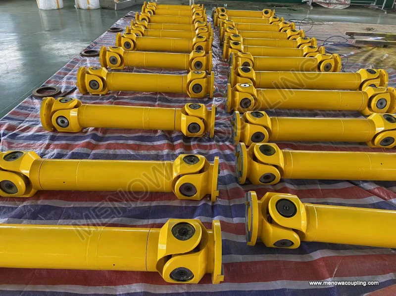
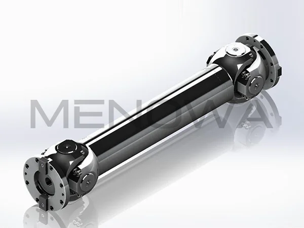
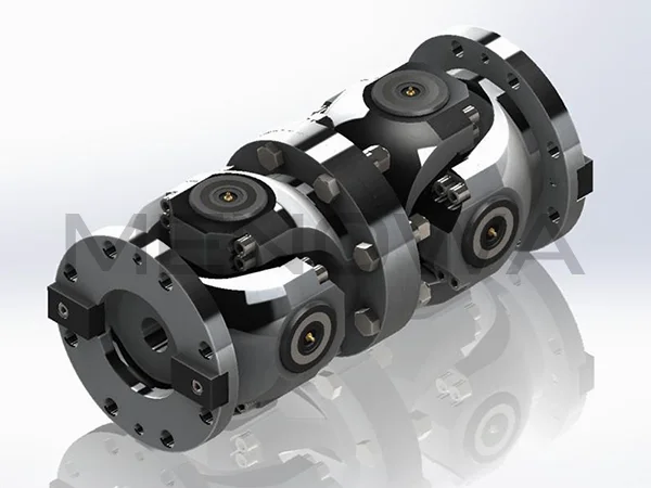
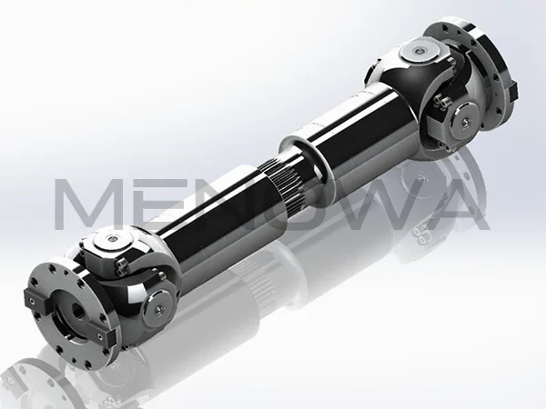
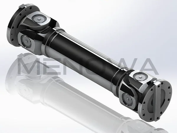
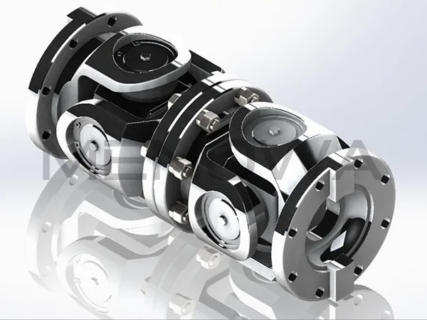
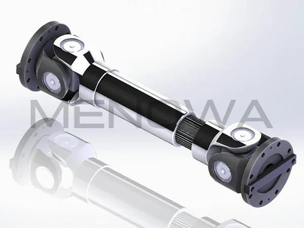
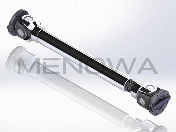
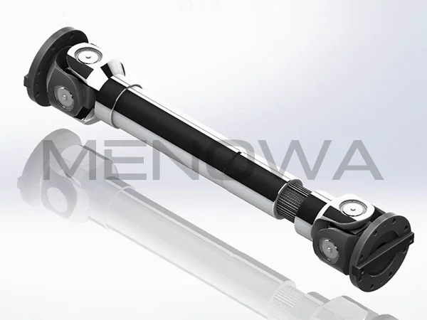
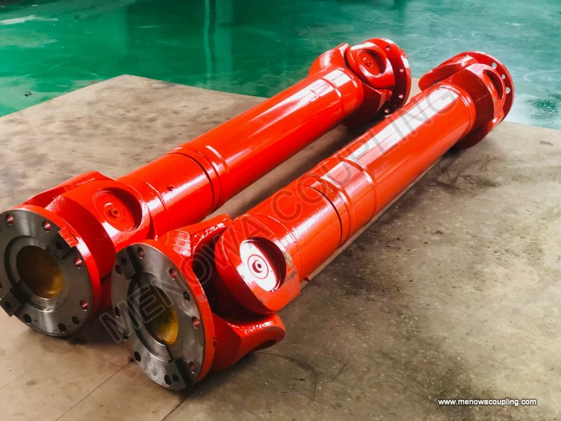
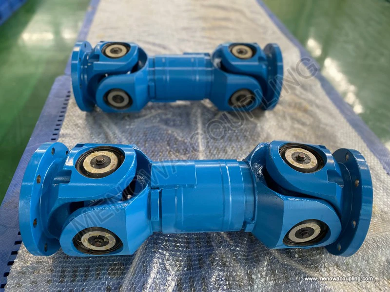
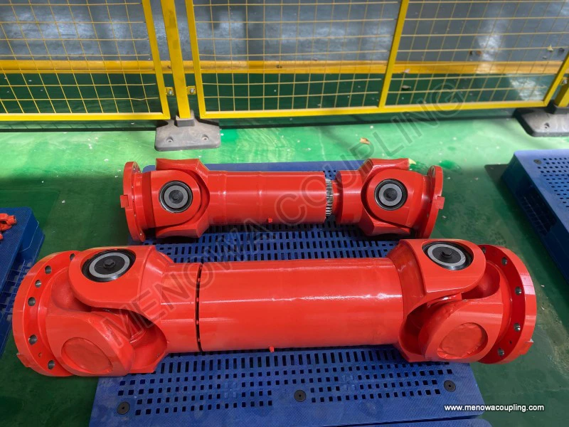
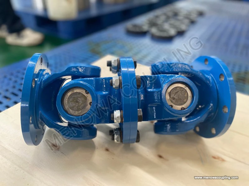
The typical structural diagram of a standard cross-axis universal coupling, the most widely used type in mechanical engineering, displays three core functional components and their assembly relationships. The primary components include two symmetrically distributed shaft yokes and a central cross-shaped intermediate shaft, also commonly referred to as a spider. The two shaft yokes are respectively fixed to the end parts of the driving shaft and the driven shaft, forming the input and output ends of power transmission. Each end of the cross-shaped intermediate shaft is equipped with a rolling bearing structure, which is nested inside the reserved mounting holes of the two yokes. The spatial layout shown in the diagram clearly reflects the orthogonal intersecting feature of the component motion axes: the four rotation centers of the cross shaft coincide at a single central point, and the two shaft yokes can perform flexible rotational deflection around the two orthogonal axes of the cross shaft respectively. This unique structural layout is the fundamental reason why the universal coupling can adapt to angular misalignment between shafts, and all subsequent motion transmission and mechanical characteristic changes are derived from this spatial structural feature.
By observing the detailed structural diagram, it can be found that the internal bearing structure of the coupling is a key detail that determines its transmission efficiency and service life. The bearings matched with the cross shaft are mostly needle roller bearings, which occupy a small radial space while providing sufficient bearing capacity and reducing friction resistance during relative motion. The diagram shows that the needle rollers are uniformly arranged between the outer wall of the cross shaft journal and the inner wall of the yoke hole, forming a rolling friction pair. This structure effectively avoids sliding friction between rigid components during shaft deflection and rotation, greatly reducing mechanical wear and energy loss. In addition, the matching gap between the cross shaft, bearings and yokes is precisely reflected in the standardized diagram design. A reasonable fit gap ensures free flexible rotation of components without excessive vibration and impact caused by loose assembly during high-speed operation, balancing the flexibility and stability of power transmission.
The working principle of the universal coupling can be fully interpreted based on its structural diagram and spatial motion relationship. When the driving shaft starts to rotate, the driving yoke fixed at its end synchronously rotates around the shaft axis, and the rotational torque is transmitted to the cross shaft through the bearing assembly. Driven by the driving yoke, the cross shaft undergoes compound motion including rotation and spatial swing, and further drives the driven yoke and the connected driven shaft to rotate synchronously. The core advantage reflected by the structural diagram is that when there is a certain included angle between the driving shaft and the driven shaft, the orthogonal axis structure of the cross shaft can continuously adjust the motion posture in real time to compensate for the angular deviation, ensuring continuous and effective transmission of rotational motion and torque. In the operation process, the deflection angle between the two shafts is not fixed; the flexible connection structure shown in the diagram can adapt to dynamic angle changes within a certain range, which enables the mechanical equipment to maintain stable power transmission even with vibration, deformation or position offset during operation.
The motion characteristic curve derived from the universal coupling diagram reveals its unique non-constant velocity transmission rule, which is a core mechanical feature that must be mastered in practical application. When the two connected shafts have a deflection angle, the angular velocity of the driven shaft will fluctuate periodically within a single rotation cycle. Specifically, when the rotation plane of the driving yoke is consistent with the deflection plane of the two shafts, the angular velocity of the driven shaft reaches the maximum value; when the driving yoke rotates to be perpendicular to the deflection plane, the angular velocity of the driven shaft drops to the minimum value. This periodic velocity fluctuation will produce corresponding torsional vibration and alternating load on the transmission system. The structural diagram clearly explains the root cause of this characteristic: the asymmetric spatial motion relationship between the cross shaft and the two yokes under angular misalignment leads to inconsistent motion conversion efficiency in different rotation stages. The larger the deflection angle between the shafts, the more obvious the angular velocity fluctuation and the greater the additional dynamic load generated.
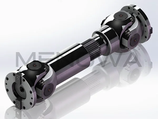
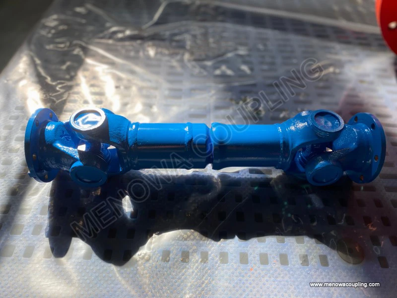
To eliminate the adverse effects of non-constant velocity transmission, the assembly diagram of a double universal coupling transmission system is often adopted in engineering practice. The diagram shows that two single universal couplings are installed at the two ends of an intermediate shaft, with the two driving yokes kept in the same plane and the deflection angles between the intermediate shaft and the two main shafts equal. This symmetric structural layout can completely offset the periodic velocity fluctuation generated by the front single coupling through the reverse fluctuation characteristic of the rear coupling, finally realizing constant-velocity synchronous transmission between the driving shaft and the driven shaft. This combined structural form inherits all the flexible connection advantages of a single universal coupling, while overcoming the defect of unstable output velocity, and is the most commonly used transmission structure in medium and long-distance shaft transmission scenarios. The diagram of the double universal coupling system also reflects the key assembly technical points, including the parallelism of the two deflection planes and the consistency of the deflection angles, which are the core prerequisites for ensuring constant-velocity transmission.
In terms of structural classification, the diagrams of different types of universal couplings show distinct structural differences and adaptive characteristics. In addition to the most common cross-axis rigid universal coupling, there are also flexible universal couplings and constant-velocity universal couplings with optimized structures. The diagram of a flexible universal coupling adds elastic deformation components inside the traditional rigid structure, which can not only adapt to angular misalignment but also absorb part of vibration and impact load during transmission, with better damping performance. The structural optimization of constant-velocity universal couplings focuses on improving the motion coordination relationship of internal components, realizing uniform angular velocity output under a single coupling state through special curved track and rolling body matching, and is more suitable for high-speed and high-precision transmission scenarios. By comparing the structural diagrams of different types of couplings, it is clear that the core design logic of all universal couplings is to use flexible spatial motion pairs to realize misalignment compensation, and the difference in component structures determines their respective applicable working conditions and mechanical performances.
The application value of the universal coupling structural diagram is reflected in multiple links of mechanical design, equipment maintenance and fault analysis. In the mechanical design stage, designers can determine the coupling model, installation position and assembly form according to the structural size, motion range and misalignment compensation capacity shown in the diagram, and complete the matching design of the transmission system. For mechanical equipment with complex motion trajectories and variable working postures, the diagram can intuitively verify whether the coupling’s flexible range can cover the dynamic displacement and angle change of the shaft system, avoiding transmission jamming and component damage caused by insufficient compensation capacity. In the equipment maintenance process, the standard structural diagram provides a clear disassembly and assembly sequence and component distribution basis, helping maintenance personnel quickly identify worn parts such as bearings and cross shafts, and complete accurate replacement and debugging.
Further analysis of the stress characteristics based on the coupling diagram shows that the internal components bear complex alternating stress during operation. The cross shaft, as the core force-bearing component, needs to withstand both the torsional load transmitted by torque and the bending load generated by shaft deflection. The bearings bear periodic impact load and friction load during rolling motion. The stress distribution rule reflected by the structural diagram indicates that the root of the cross shaft journal and the bearing contact area are the most vulnerable parts to wear and fatigue damage. This mechanical feature provides a theoretical basis for the improvement of coupling processing technology and material selection. High-strength alloy materials and surface strengthening processes are usually adopted for key components to improve their fatigue resistance and wear resistance, ensuring stable operation under long-term alternating load conditions.
In practical engineering operation, the installation accuracy shown in the universal coupling diagram directly affects the operating state and service life of the transmission system. The standard assembly diagram requires that the deflection angle of the coupling should be controlled within the rated allowable range. Excessively large deflection angles will not only amplify angular velocity fluctuation and increase system vibration, but also sharply increase the wear rate of internal bearings and cross shafts, leading to early failure of components. At the same time, the coaxiality and parallelism of the shafts should be adjusted according to the diagram specifications to avoid additional eccentric load caused by installation deviation. Reasonable installation and debugging based on structural diagram standards can effectively reduce system energy consumption, reduce mechanical noise, and extend the overall service life of the transmission system.
With the continuous development of mechanical transmission technology, the structural design of universal couplings is also constantly optimized and upgraded on the basis of traditional structural diagrams. Modern optimized universal coupling structures adopt more compact spatial layouts and high-precision matching structures, which further improve the misalignment compensation range and transmission efficiency while reducing the overall structural size. Some improved structures optimize the lubrication channel design based on the traditional diagram, realizing more uniform lubrication of internal friction pairs and reducing component wear. In addition, lightweight structural optimization design makes the coupling more adaptable to high-speed and mobile mechanical equipment, meeting the development needs of modern machinery for high efficiency, low energy consumption and high reliability.
In summary, the diagram of a universal coupling is not only a visual display of its structural form, but also a concentrated embodiment of its motion principle, mechanical characteristics and engineering application logic. The unique orthogonal flexible connection structure composed of yokes and cross shafts constitutes the core foundation of its misalignment compensation and flexible transmission function. Whether in traditional mechanical transmission systems or modern intelligent mechanical equipment, universal couplings always play an irreplaceable role in connecting misaligned shafts and realizing stable power transmission. In-depth understanding and analysis of the universal coupling diagram can help engineering personnel accurately grasp its operating characteristics, standardize installation and use, optimize system matching, and provide strong technical support for the stable and efficient operation of various mechanical transmission systems. With the continuous innovation of mechanical structure design and manufacturing technology, the structural performance of universal couplings will be further improved, and their application scope in various industrial fields will continue to be expanded.
Post Date: May 26, 2026
https://www.menowacoupling.com/china-coupling/diagram-of-universal-coupling.html
Products
Tags
Supply
Related Articles
Universal Coupling Wholesale
In the global mechanical transmission industry, universal couplings have emerged as indispensable core components for power transmission systems, widely favored by downstream manufacturing, engineering, and transportation sectors across international markets. As global industrialization continues to advance and mechanic…Working Principle of Universal Coupling
A universal coupling, also widely known as a universal joint, is a fundamental mechanical transmission component designed to solve the core problem of power transmission between two non-collinear rotating shafts. Unlike rigid couplings that only work efficiently when connected shafts maintain perfect coaxial alignment, …Gap Chart of Universal Coupling
The operational stability and transmission accuracy of universal couplings are fundamentally determined by the internal gap distribution between mating components, making gap chart analysis a core technical method for evaluating assembly quality, predicting operating performance, and optimizing structural design. A univ…Universal Coupling For Ball Mill
In the complex and demanding operating environment of mineral processing, building materials production, chemical raw material grinding and other heavy industrial fields, ball mills stand as core processing equipment responsible for crushing and grinding various bulk raw materials into fine particles and powders that me…Universal Coupling Fabrication
Universal coupling fabrication stands as a foundational discipline within mechanical manufacturing, focusing on the precise production of flexible shaft connection components that enable reliable torque transmission between misaligned rotating shafts. As a core mechanical component widely adopted in power transmission s…Maintenance of Universal Coupling
Universal couplings serve as indispensable connecting components in mechanical transmission systems, designed to transmit rotational torque between two shafts that operate with angular misalignment, parallel offset, or variable positional relationships. Widely applied in industrial transmission equipment, mechanical eng…
 WeChat
 WhatsApp