Universal Coupling Manufacture
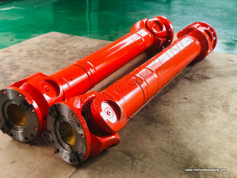
In the complex landscape of mechanical power transmission, universal couplings stand out as indispensable components that bridge the gap between misaligned shafts, enabling the seamless transfer of torque and rotational motion across a wide range of industrial and mechanical applications. Unlike rigid couplings that demand precise alignment between connected shafts, universal couplings are engineered to accommodate angular, axial, and in some cases, radial misalignments, making them versatile solutions for scenarios where perfect shaft alignment is either impractical or impossible to maintain. From automotive drive systems and heavy industrial machinery to precision instruments and aerospace equipment, these couplings play a critical role in ensuring the reliability and efficiency of power transmission, adapting to the dynamic demands of diverse operating environments. The manufacture of universal couplings is a sophisticated process that integrates material science, mechanical engineering, and precision manufacturing techniques, with each step carefully designed to meet the rigorous performance requirements of modern machinery. Every stage, from raw material selection to final assembly and testing, contributes to the overall quality, durability, and functionality of the end product, requiring meticulous attention to detail and adherence to strict manufacturing principles.
The foundation of high-quality universal coupling manufacture lies in the careful selection of raw materials, as the performance of the coupling is directly determined by the mechanical properties of the materials used. Since universal couplings are required to withstand alternating loads, impact forces, and continuous rotational stress, the materials must possess high strength, wear resistance, fatigue resistance, and appropriate toughness to avoid premature failure. The most commonly used materials for universal coupling components are high-quality alloy steels, including 45 steel, 40 chromium, 42CrMo, and 50Cr, which offer an excellent balance of strength and ductility when subjected to proper heat treatment. These alloy steels are preferred for their ability to withstand heavy loads and resist wear, making them ideal for the core components of universal couplings such as yokes, cross shafts, and bearings. For applications that require enhanced corrosion resistance, such as those in marine, chemical, or food processing industries, high-strength stainless steel, such as 316L, is often used. This material contains molybdenum, which significantly improves its resistance to pitting and corrosion in harsh environments, ensuring long-term reliability even in corrosive media. In some high-precision or lightweight applications, such as aerospace or robotics, aluminum alloys like 7075-T6 are employed due to their high strength-to-weight ratio, which reduces rotational inertia and improves dynamic response. Engineering plastics are also used in certain low-load, low-speed applications, offering self-lubricating properties and excellent vibration damping, though their strength limitations require careful structural design to compensate. The selection of raw materials is not a one-size-fits-all process; instead, it is tailored to the specific application requirements, including load capacity, operating temperature, environmental conditions, and precision demands, ensuring that the final product can perform optimally in its intended use.
Once the raw materials have been selected and inspected, the next step in the manufacturing process is blank forming, which converts the raw materials into rough shapes that closely resemble the final components. This stage is critical as it lays the groundwork for the subsequent machining processes, and any defects introduced during blank forming can significantly impact the quality of the finished product. The two primary methods used for blank forming in universal coupling manufacture are forging and casting, each with its own advantages and applications. Forging is the preferred method for components that need to withstand heavy loads and high stress, such as yokes and cross shafts. This process involves heating the raw material to a high temperature, typically between 800 and 1200 degrees Celsius, to improve its plasticity and ductility. The heated material is then subjected to high-pressure impact or extrusion, either through free forging or die forging, to shape it into the desired form. Forging refines the grain structure of the metal, increasing its density and strength, and eliminates internal defects such as porosity and inclusions, resulting in components with superior mechanical properties. After forging, the blanks are subjected to a slow cooling process to relieve internal stresses, which prevents cracking and deformation. Casting, on the other hand, is used for components with complex shapes that are difficult to achieve through forging. This method involves melting the raw material and pouring it into a mold that matches the shape of the desired component. The molten metal is then allowed to cool and solidify, forming the blank. However, casting can introduce defects such as shrinkage, porosity, and cracks if the mold design, pouring temperature, or cooling rate is not carefully controlled. To ensure the quality of cast blanks, strict control over the mold material, pouring process, and cooling conditions is essential. Regardless of the forming method used, all blanks undergo a thorough inspection to identify any surface or internal defects, which are either repaired or discarded to prevent further processing of faulty components.
Following blank forming, the components move on to the machining stage, which is crucial for achieving the precise dimensions, surface finish, and geometric accuracy required for proper assembly and performance. Machining is a multi-step process that involves removing excess material from the blank to shape it into the final component, with each step designed to refine the dimensions and improve the surface quality. The first step in machining is rough machining, which removes the majority of the excess material from the blank, establishing the basic shape and dimensions of the component. Common rough machining processes include turning, milling, and drilling, which are performed using high-speed cutting tools to efficiently remove material. During rough machining, the cutting parameters, such as cutting speed, feed rate, and depth of cut, are carefully controlled to avoid excessive cutting forces that could cause workpiece deformation or tool wear. After rough machining, the components undergo semi-finishing, which further refines the dimensions and surface quality, bringing them closer to the final specifications. This stage typically involves more precise cutting tools and lower cutting speeds to reduce surface roughness and improve dimensional accuracy. The final step in machining is finishing, which is the most critical stage for achieving the required precision. For key components such as cross shaft journals and yoke pin holes, finishing processes include precision turning, grinding, and honing, which can achieve dimensional tolerances within microns. For example, the journal of a cross shaft may require a cylindricality error of less than 0.005 millimeters and a surface roughness of Ra 0.8 micrometers or lower to ensure proper fit with bearings and reduce wear during operation. Additionally, components that require assembly, such as yokes with mounting holes, undergo drilling, tapping, and reaming processes to ensure the position accuracy and thread quality of the assembly holes. Throughout the machining process, precision measuring tools such as calipers, micrometers, and coordinate measuring machines are used to verify the dimensions and geometric accuracy of the components, ensuring that they meet the design specifications. Any components that do not meet the required tolerances are either reworked or discarded, as even minor deviations can lead to poor assembly, increased wear, and premature failure of the universal coupling.
After machining, the components undergo heat treatment, a critical process that modifies the internal structure of the metal to enhance its mechanical properties, including hardness, strength, wear resistance, and fatigue life. The type of heat treatment applied depends on the material of the component and its intended function. For example, cross shafts and yokes, which are subjected to high loads and wear, typically undergo quenching and tempering (also known as tempering). Quenching involves heating the component to a high temperature, usually above the critical point of the metal, and then rapidly cooling it in a quenching medium such as oil or water. This process hardens the metal by forming a martensitic structure, but it also increases brittleness. To reduce brittleness and improve toughness, the component is then tempered by heating it to a lower temperature and holding it for a specific period before cooling it slowly. This tempering process balances the hardness and toughness of the component, ensuring that it can withstand heavy loads and impact without cracking. For components that require a hard surface and a tough core, such as bearing surfaces, surface hardening processes such as induction hardening or carburizing are used. Induction hardening involves heating the surface of the component using an electromagnetic field, followed by rapid quenching, which hardens the surface while leaving the core relatively soft and tough. Carburizing involves heating the component in a carbon-rich atmosphere, which diffuses carbon into the surface layer, followed by quenching and tempering to achieve a hard, wear-resistant surface. The heat treatment process requires precise control over heating temperature, holding time, and cooling rate, as any deviations can result in components with inconsistent mechanical properties, such as uneven hardness or cracking. After heat treatment, the components are inspected to verify their hardness and microstructure, ensuring that they meet the required performance standards.
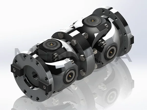
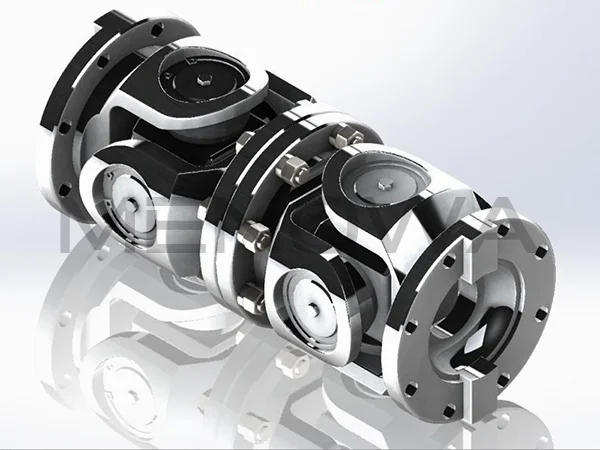
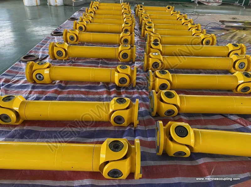
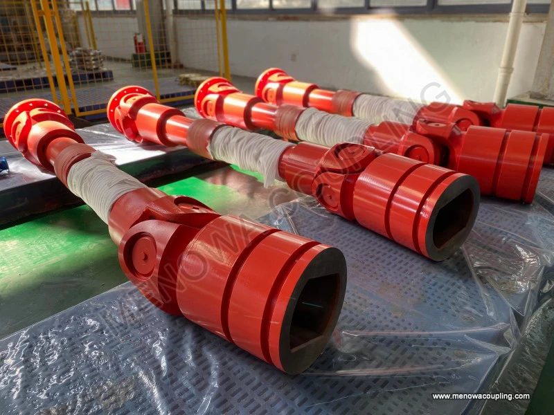
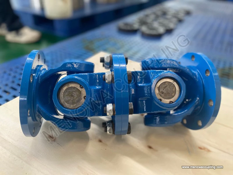
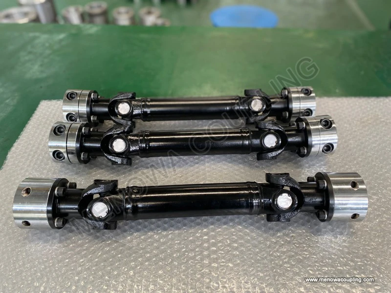
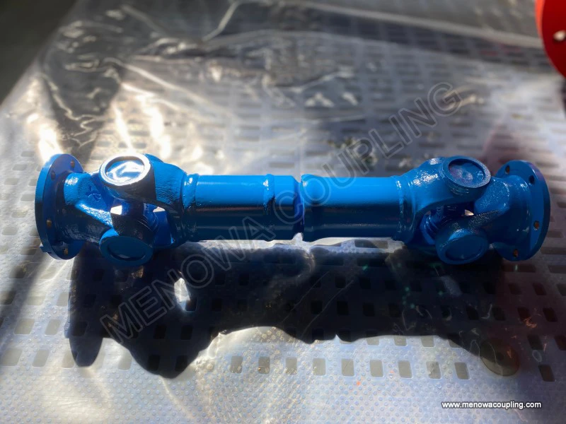
Once the individual components have been machined and heat treated, they move on to the assembly stage, where they are combined to form the complete universal coupling. Assembly is a meticulous process that requires careful attention to detail to ensure that all components fit together properly and function as intended. The first step in assembly is cleaning, where all components are thoroughly cleaned to remove any oil, grease, metal chips, or other contaminants that could affect the fit or performance of the coupling. This is typically done using ultrasonic cleaning or solvent cleaning, followed by drying to ensure that no residue remains. After cleaning, the components are assembled in a specific sequence: first, the bearings are installed into the yoke holes, then the cross shaft is inserted into the bearings, and finally, the other yoke is attached to the cross shaft. During assembly, it is important to ensure that the bearings are properly lubricated to reduce friction and wear, and that the cross shaft rotates freely within the yokes without binding. The assembly process also involves adjusting the fit between components to ensure the correct assembly clearance; excessive clearance can lead to increased vibration and noise during operation, while insufficient clearance can restrict movement and cause premature wear. In some cases, fasteners such as bolts or pins are used to secure the components together, and these fasteners are torqued to specific values to ensure a secure connection. After assembly, the complete universal coupling undergoes a series of tests to verify its performance and quality. These tests include dimensional inspection to ensure that the coupling meets the design specifications, rotational testing to check for smooth operation and any abnormal noise or vibration, and torque testing to verify the load-carrying capacity. For high-precision applications, dynamic balancing tests are also performed to ensure that the coupling rotates evenly at high speeds, reducing vibration and extending the life of the coupling and the connected machinery.
Quality control is an integral part of every stage of universal coupling manufacture, ensuring that the final product meets the highest standards of performance and reliability. From the initial inspection of raw materials to the final testing of the assembled coupling, quality control measures are implemented to identify and eliminate any defects. Raw materials are inspected for chemical composition, mechanical properties, and surface quality using techniques such as spectral analysis, tensile testing, and impact testing. This ensures that the materials meet the required specifications and are free from defects such as cracks, inclusions, or surface imperfections. During blank forming, visual inspections and non-destructive testing methods such as ultrasonic testing or magnetic particle testing are used to detect internal and surface defects in the blanks. Machining processes are monitored to ensure that the components meet the required dimensional tolerances and surface finish, with regular inspections using precision measuring tools. Heat treatment processes are controlled and monitored to ensure that the components achieve the desired hardness and microstructure, with hardness testing and metallographic analysis performed to verify the results. Assembly is inspected to ensure that all components are properly fitted and lubricated, and that the coupling operates smoothly. Final testing includes torque testing, rotational testing, and dynamic balancing, as well as visual inspection to ensure that the coupling is free from any defects such as scratches, dents, or misalignment. Any components or couplings that fail to meet the quality standards are either reworked or discarded, ensuring that only high-quality products are delivered to customers.
The manufacture of universal couplings is also influenced by technological advancements and evolving industry demands. In recent years, the adoption of computer numerical control (CNC) machining has revolutionized the manufacturing process, allowing for greater precision, consistency, and efficiency. CNC machines can perform complex machining operations with high accuracy, reducing human error and improving the quality of the components. Additionally, the use of advanced materials, such as high-strength alloys and composite materials, has expanded the performance capabilities of universal couplings, allowing them to withstand higher loads, higher speeds, and more harsh operating environments. The development of new heat treatment technologies, such as vacuum heat treatment, has also improved the quality and consistency of the heat treatment process, reducing the risk of defects and enhancing the mechanical properties of the components. Another trend in universal coupling manufacture is the customization of products to meet specific application requirements. Many industries require universal couplings with unique dimensions, load capacities, or environmental resistance, and manufacturers are increasingly offering customized solutions to meet these needs. This involves modifying the design, material selection, and manufacturing processes to create couplings that are tailored to the specific needs of the customer, ensuring optimal performance in their intended application.
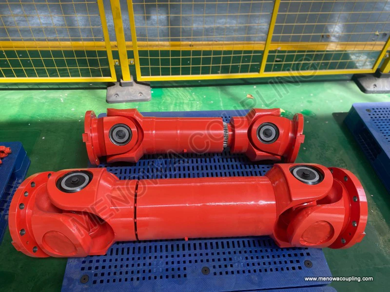
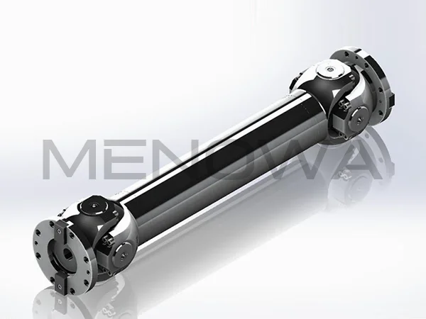
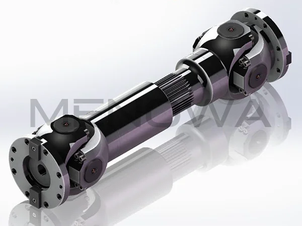
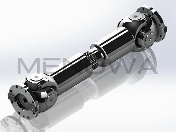
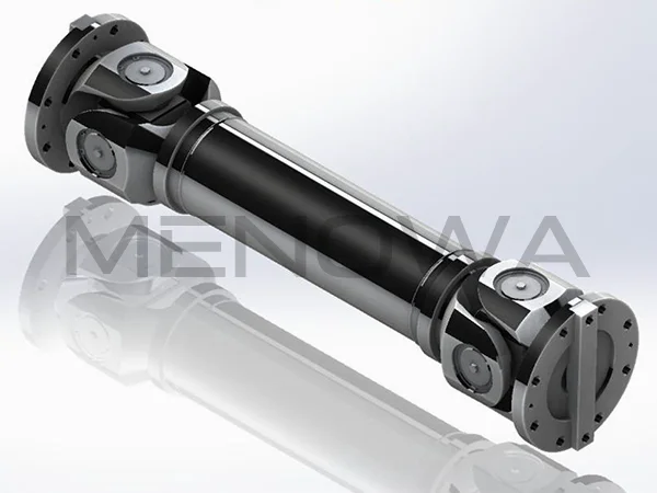
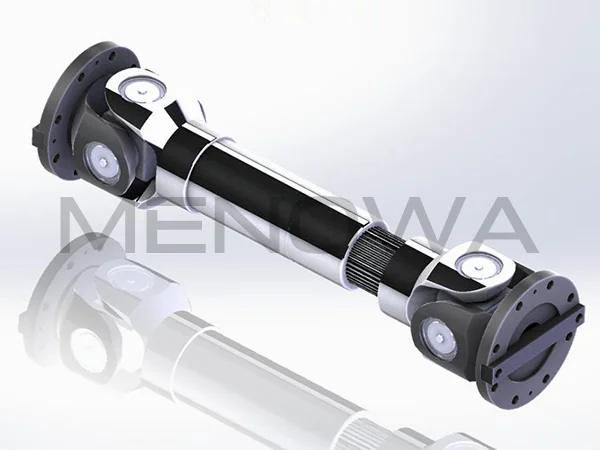
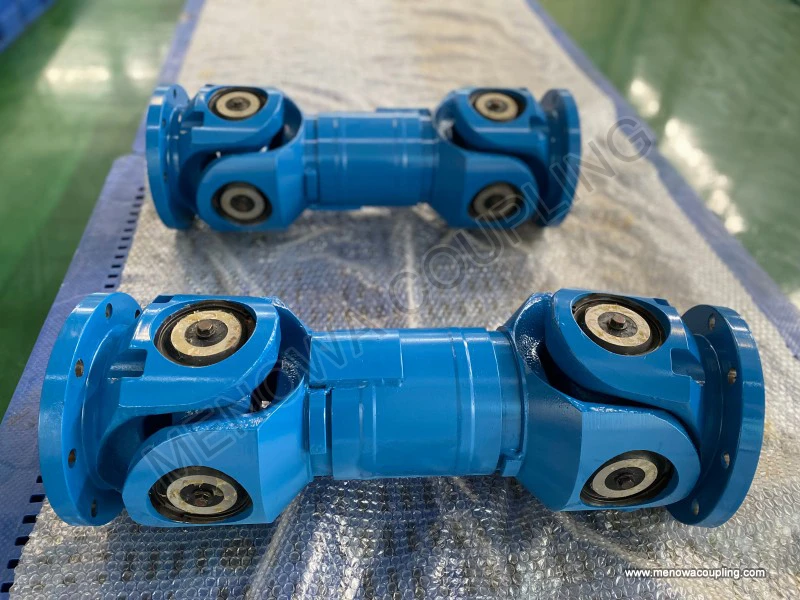
It is important to note that while universal couplings offer numerous advantages, including excellent angular compensation and high torque transmission capabilities, they also have certain limitations that must be considered during the manufacturing process. For example, a single cross-axis universal coupling may experience speed fluctuations during transmission, which can cause vibration and noise in precision applications. To address this issue, manufacturers often produce double-joint universal couplings, which use two universal couplings arranged in a specific geometric configuration to eliminate speed fluctuations and ensure synchronous rotation of the input and output shafts. Another limitation is the wear of components such as bearings and cross shafts, which can reduce the service life of the coupling if not properly addressed. To mitigate this, manufacturers use high-wear-resistant materials, proper lubrication, and advanced surface treatment technologies to extend the service life of the components. Additionally, universal couplings require regular maintenance, including lubrication and inspection, to ensure optimal performance, and manufacturers often provide guidelines for maintenance to help customers maximize the service life of their products.
In conclusion, the manufacture of universal couplings is a complex and sophisticated process that requires expertise in material science, mechanical engineering, and precision manufacturing. From the careful selection of raw materials to the final assembly and testing, each step is critical to ensuring the quality, durability, and performance of the end product. The use of advanced manufacturing technologies, strict quality control measures, and continuous innovation has allowed manufacturers to produce universal couplings that meet the diverse and evolving needs of modern industry. As industrial machinery becomes more advanced and demanding, the manufacture of universal couplings will continue to evolve, with a focus on improving performance, reducing weight, enhancing durability, and offering customized solutions. Whether used in heavy industrial machinery, automotive drive systems, precision instruments, or aerospace equipment, universal couplings play a vital role in ensuring the reliable and efficient transmission of power, making them an indispensable component in the world of mechanical engineering. The commitment to quality and innovation in universal coupling manufacture ensures that these components will continue to support the growth and development of various industries for years to come.
Post Date: Apr 29, 2026
https://www.menowacoupling.com/china-coupling/universal-coupling-manufacture.html
Products
Tags
Supply
Related Articles
Universal Coupling Exporter
As a vital component in mechanical transmission systems, universal couplings play an irreplaceable role in connecting two shafts that are not in the same axis or have relative displacement, ensuring stable and efficient torque transmission. For universal coupling exporters, understanding the product’s working principle…Universal Coupling For Ball Mill
In the complex and demanding operating environment of mineral processing, building materials production, chemical raw material grinding and other heavy industrial fields, ball mills stand as core processing equipment responsible for crushing and grinding various bulk raw materials into fine particles and powders that me…Characteristics of Universal Coupling
A universal coupling, also commonly referred to as a universal joint or U-joint, is a critical mechanical component designed to connect two rigid shafts whose axes are inclined to each other, enabling the transmission of rotary motion and torque even when the shafts are not perfectly aligned. This versatile component ha…Types of Universal Coupling
In the complex and interconnected mechanical transmission systems that power modern industrial production, automotive operation, engineering machinery movement, and various precision mechanical equipment, universal couplings stand as indispensable basic mechanical components that undertake the core task of transmitting …Universal Coupling For Sale
A universal coupling, also commonly referred to as a universal joint or U-joint, is a critical mechanical component designed to connect two rigid shafts whose axes are inclined to each other, enabling the transmission of rotary motion and torque even when there is a misalignment between the two shafts. This versatile co…Size Chart of Universal Coupling
A universal coupling, also known as a universal joint, is a critical mechanical component designed to transmit torque between two shafts that are not aligned perfectly, allowing for angular misalignment while maintaining efficient power transfer. The size chart of a universal coupling serves as a fundamental reference t…
 WeChat
 WhatsApp