Size Chart of Universal Coupling
A universal coupling, also known as a universal joint, is a critical mechanical component designed to transmit torque between two shafts that are not aligned perfectly, allowing for angular misalignment while maintaining efficient power transfer. The size chart of a universal coupling serves as a fundamental reference tool for engineers, technicians, and maintenance professionals, providing precise dimensional data that ensures proper selection, installation, and performance of the coupling in various industrial and mechanical applications. Understanding how to interpret and use a universal coupling size chart is essential to avoid mismatches, reduce wear and tear, and maximize the service life of both the coupling and the connected equipment. This article explores the key elements of a universal coupling size chart, the significance of each dimension, how to measure and match sizes accurately, and the practical considerations that influence size selection across different applications.
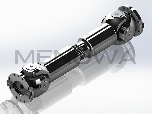
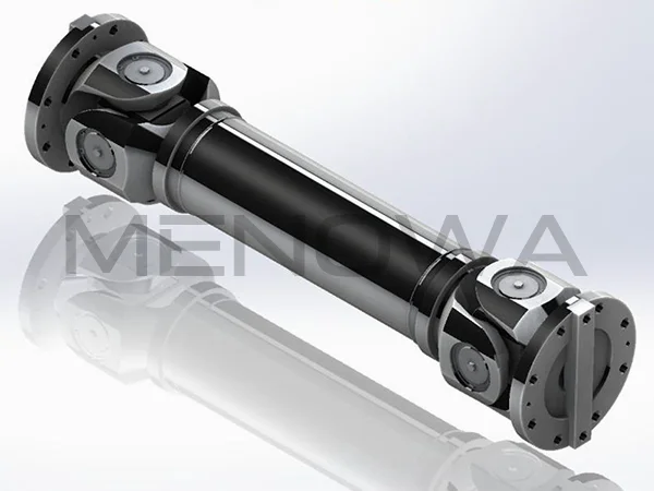
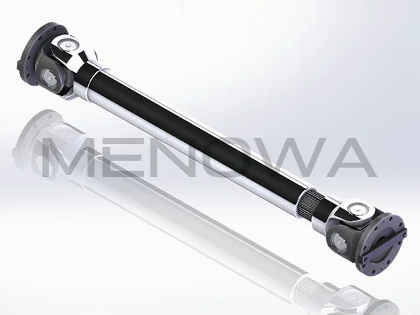
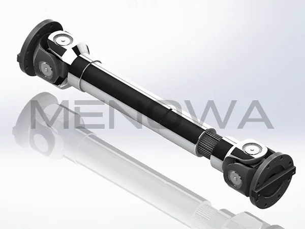
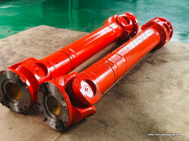
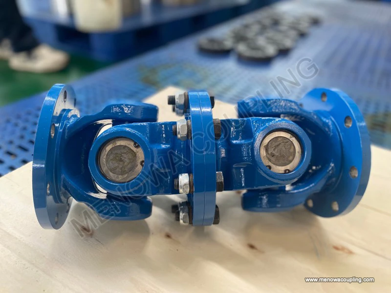
The size chart of a universal coupling is not a one-size-fits-all document; it varies significantly based on the type of universal coupling, the materials used in its construction, and the specific application requirements. Universal couplings come in several common types, including cross-type (also known as cardan joints), ball-and-socket types, and flexible universal couplings, each with its own unique dimensional characteristics. Cross-type universal couplings, which are the most widely used in heavy-duty applications such as industrial machinery, automotive drives, and agricultural equipment, have a size chart that focuses on dimensions related to the cross shaft, bearing caps, yokes, and the overall length of the coupling. Ball-and-socket universal couplings, on the other hand, have size charts that emphasize the diameter of the ball, the depth of the socket, and the length of the connecting shafts, as these dimensions directly impact the angular misalignment capacity and torque transmission efficiency.
At the core of any universal coupling size chart are the key dimensional parameters that define the coupling’s physical characteristics and performance capabilities. These parameters include the bore diameter, shaft diameter, overall length, cross shaft diameter, bearing cap diameter, yoke width, and angular misalignment capacity. Each of these dimensions plays a critical role in ensuring that the coupling fits seamlessly with the connected shafts and operates within the required performance limits. The bore diameter, for example, is the inner diameter of the coupling’s hubs, which must match the outer diameter of the shafts it connects. A mismatch in bore diameter can lead to loose connections, excessive vibration, and premature failure of both the coupling and the shafts. Similarly, the shaft diameter, which refers to the outer diameter of the coupling’s output shafts (if applicable), must be compatible with the driven or driving components, such as gears, motors, or pumps.
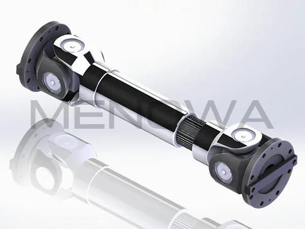
The overall length of the universal coupling is another critical dimension included in the size chart. This dimension is measured from the end of one hub to the end of the other hub and determines the space required for installation. In applications where space is limited, such as in compact machinery or automotive drivetrains, selecting a coupling with the appropriate overall length is essential to avoid interference with other components. The cross shaft diameter, specific to cross-type universal couplings, is the diameter of the central cross that connects the two yokes. This dimension directly influences the torque capacity of the coupling—larger cross shaft diameters can transmit higher torques, making them suitable for heavy-duty applications, while smaller diameters are ideal for light-duty use.
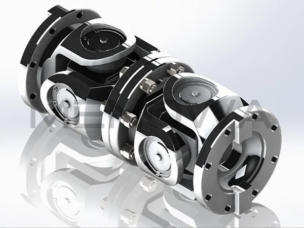
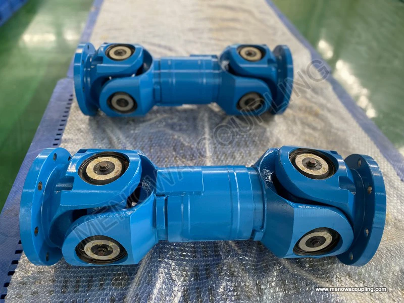
Bearing cap diameter is another key parameter in the size chart, particularly for cross-type universal couplings. The bearing caps house the bearings that allow the cross shaft to rotate freely, and their diameter must be precise to ensure proper bearing fit and smooth operation. A bearing cap that is too small will cause the bearings to be compressed, leading to increased friction and overheating, while a cap that is too large will result in loose bearings, leading to excessive play and vibration. The yoke width, which is the distance between the two arms of the yoke, also affects the coupling’s performance. Wider yokes provide greater stability and can handle higher angular misalignments, while narrower yokes are more compact but have limited misalignment capacity.
Angular misalignment capacity is a critical performance parameter included in most universal coupling size charts, though it is not always a physical dimension. This parameter specifies the maximum angle at which the two connected shafts can be misaligned while the coupling still operates efficiently. For cross-type universal couplings, the typical angular misalignment capacity ranges from 5 degrees to 45 degrees, depending on the size and design. Ball-and-socket universal couplings often have a higher misalignment capacity, sometimes up to 90 degrees, making them suitable for applications where shafts are significantly misaligned. Understanding this parameter is essential for selecting a coupling that can accommodate the specific misalignment conditions of the application, as exceeding the maximum misalignment capacity will lead to increased wear, reduced torque transmission, and potential coupling failure.
In addition to these core dimensions, many universal coupling size charts also include additional parameters such as torque capacity, operating speed, and material specifications. Torque capacity refers to the maximum amount of torque that the coupling can transmit without failure, and it is directly related to the size and material of the coupling. Larger couplings made from high-strength materials, such as alloy steel or stainless steel, have higher torque capacities than smaller couplings made from mild steel or aluminum. Operating speed is another important parameter, as it specifies the maximum rotational speed at which the coupling can operate safely. Exceeding the recommended operating speed can cause excessive centrifugal force, leading to vibration, noise, and premature failure.
Material specifications are also often included in size charts, as the material of the coupling affects its strength, durability, and resistance to corrosion and wear. Common materials used in universal couplings include carbon steel, alloy steel, stainless steel, and aluminum. Carbon steel is the most widely used material for general-purpose applications, offering a good balance of strength and cost. Alloy steel is used for heavy-duty applications that require higher torque capacity and durability, while stainless steel is ideal for applications in corrosive environments, such as marine or chemical processing. Aluminum is used for light-duty applications where weight is a concern, such as in automotive or aerospace components.
To effectively use a universal coupling size chart, it is essential to know how to measure the relevant dimensions accurately. Measuring the bore diameter requires the use of a caliper or micrometer, which should be placed across the inner diameter of the hub to get a precise reading. It is important to measure at multiple points around the bore to ensure that it is round and that the diameter is consistent. The shaft diameter should be measured in the same way, using a caliper to measure the outer diameter of the shaft that will be connected to the coupling. The overall length of the coupling can be measured using a tape measure or ruler, from the end of one hub to the end of the other. For cross-type couplings, the cross shaft diameter and bearing cap diameter can be measured using a caliper, while the yoke width is measured as the distance between the two arms of the yoke.
When measuring, it is important to use the correct tools and to take multiple measurements to ensure accuracy. Even small variations in measurements can lead to significant mismatches, which can affect the performance and longevity of the coupling. For example, a difference of just a few thousandths of an inch in the bore diameter can result in a loose or tight fit, leading to vibration or premature wear. It is also important to consider the tolerance levels specified in the size chart, as these indicate the acceptable range of variation for each dimension. Tolerances are typically expressed as a range, such as ±0.001 inches, and ensure that the coupling will fit properly even with minor manufacturing variations.
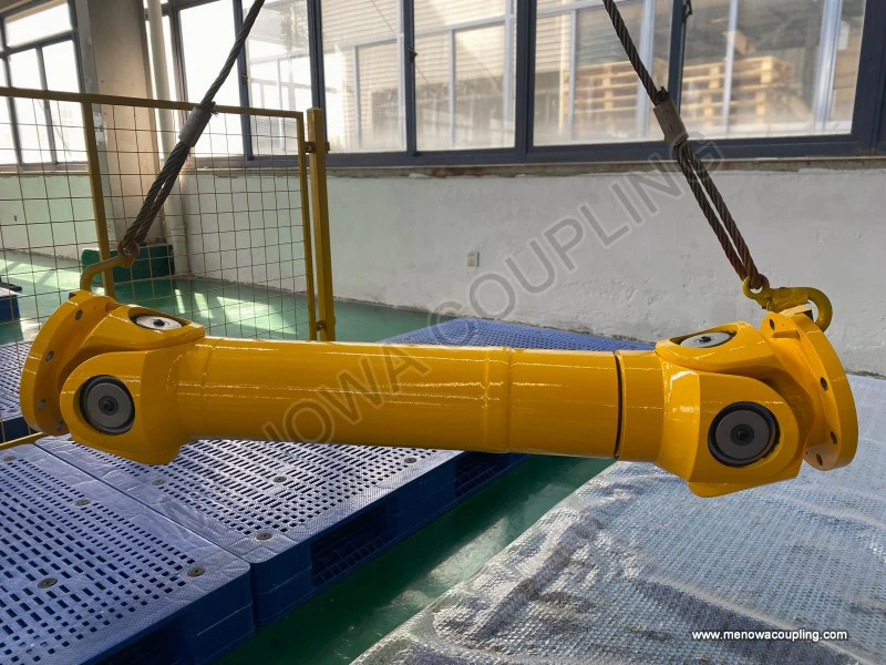
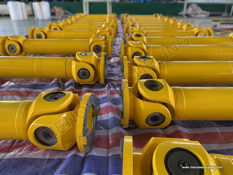
Another important consideration when using a universal coupling size chart is the application context. Different applications have different requirements for torque, speed, misalignment, and environmental conditions, all of which influence the selection of the correct coupling size. For example, in heavy-duty industrial applications such as mining or construction machinery, the coupling must be large enough to handle high torques and withstand harsh operating conditions, so the size chart should be used to select a coupling with a large cross shaft diameter, high torque capacity, and durable materials. In contrast, in light-duty applications such as small pumps or electric motors, a smaller coupling with a lower torque capacity may be sufficient, and the size chart can be used to find a compact, lightweight option.
Automotive applications present unique challenges for universal coupling size selection, as the coupling must accommodate both angular misalignment and axial movement. In automotive drivetrains, for example, the universal coupling connects the transmission to the drive shaft, and it must handle the misalignment caused by the suspension movement and the angle between the transmission and the differential. The size chart for automotive universal couplings typically includes dimensions such as the cap diameter, yoke width, and overall length, as well as torque capacity and operating speed, to ensure compatibility with the specific vehicle model and drivetrain configuration.
Marine applications also require careful size selection, as the coupling must withstand corrosive saltwater environments and transmit high torques from the engine to the propeller. In these applications, the size chart should be used to select a coupling made from corrosion-resistant materials such as stainless steel, with a high torque capacity and a design that can accommodate the misalignment between the engine and the propeller shaft. Additionally, the size chart may include parameters related to the coupling’s ability to handle axial movement, which is common in marine drivetrains due to thermal expansion and engine movement.
It is also important to consider the type of connection between the coupling and the shafts when using the size chart. Universal couplings can be connected to shafts using various methods, including keyways, set screws, clamping collars, or splines. The size chart may include dimensions related to these connection methods, such as the size of the keyway, the number of set screws, or the spline diameter. For example, a coupling with a keyway connection will have a size chart that specifies the keyway width and depth, which must match the key on the shaft to ensure a secure connection. Similarly, a splined coupling will have a size chart that specifies the number of splines and the spline diameter, which must be compatible with the splined shaft.
Maintenance and replacement are additional factors that influence the use of a universal coupling size chart. When replacing a worn or damaged coupling, it is essential to match the dimensions of the original coupling to ensure compatibility with the existing shafts and equipment. The size chart can be used to identify the correct dimensions, such as bore diameter, overall length, and cross shaft diameter, to ensure that the replacement coupling fits properly and operates as intended. In some cases, minor variations in dimensions may be acceptable, but it is important to consult the size chart and the manufacturer’s guidelines to avoid mismatches.
Common mistakes when using a universal coupling size chart include ignoring tolerance levels, using incorrect measurement tools, and failing to consider the application’s specific requirements. For example, using a tape measure instead of a caliper to measure the bore diameter can lead to inaccurate readings, resulting in a coupling that does not fit properly. Ignoring tolerance levels can also lead to mismatches, as even small variations outside the acceptable range can affect the coupling’s performance. Additionally, failing to consider the application’s torque and speed requirements can result in selecting a coupling that is too small, leading to premature failure, or too large, leading to unnecessary cost and space consumption.
To avoid these mistakes, it is important to follow a systematic approach when using a universal coupling size chart. First, identify the type of universal coupling required for the application, as different types have different size charts. Next, measure the relevant dimensions of the shafts and the installation space using accurate tools such as calipers or micrometers. Then, refer to the size chart to find a coupling that matches these dimensions, ensuring that the torque capacity, operating speed, and misalignment capacity meet the application’s requirements. Finally, verify the tolerance levels to ensure that the coupling will fit properly, even with minor manufacturing variations.
In conclusion, the size chart of a universal coupling is an indispensable tool for anyone involved in the selection, installation, or maintenance of mechanical systems that use universal couplings. It provides precise dimensional data that ensures the coupling fits properly with the connected shafts, operates within the required performance limits, and maximizes service life. By understanding the key dimensions included in the size chart, how to measure them accurately, and how to match them to the application’s requirements, engineers and technicians can select the right universal coupling for any application, from light-duty electric motors to heavy-duty industrial machinery. Whether working in automotive, marine, industrial, or agricultural settings, a thorough understanding of the universal coupling size chart is essential to ensure efficient, reliable, and safe operation of mechanical systems.
Post Date: Apr 29, 2026
https://www.menowacoupling.com/china-coupling/size-chart-of-universal-coupling.html
Products
Tags
Supply
Related Articles
Universal Coupling Exporter
As a vital component in mechanical transmission systems, universal couplings play an irreplaceable role in connecting two shafts that are not in the same axis or have relative displacement, ensuring stable and efficient torque transmission. For universal coupling exporters, understanding the product’s working principle…Universal Coupling For Ball Mill
In the complex and demanding operating environment of mineral processing, building materials production, chemical raw material grinding and other heavy industrial fields, ball mills stand as core processing equipment responsible for crushing and grinding various bulk raw materials into fine particles and powders that me…Characteristics of Universal Coupling
A universal coupling, also commonly referred to as a universal joint or U-joint, is a critical mechanical component designed to connect two rigid shafts whose axes are inclined to each other, enabling the transmission of rotary motion and torque even when the shafts are not perfectly aligned. This versatile component ha…Types of Universal Coupling
In the complex and interconnected mechanical transmission systems that power modern industrial production, automotive operation, engineering machinery movement, and various precision mechanical equipment, universal couplings stand as indispensable basic mechanical components that undertake the core task of transmitting …Universal Coupling For Sale
A universal coupling, also commonly referred to as a universal joint or U-joint, is a critical mechanical component designed to connect two rigid shafts whose axes are inclined to each other, enabling the transmission of rotary motion and torque even when there is a misalignment between the two shafts. This versatile co…Universal Coupling Manufacture
In the complex landscape of mechanical power transmission, universal couplings stand out as indispensable components that bridge the gap between misaligned shafts, enabling the seamless transfer of torque and rotational motion across a wide range of industrial and mechanical applications. Unlike rigid couplings that dem…
 WeChat
 WhatsApp