Gap Chart of Elastic Coupling
In the realm of mechanical power transmission, elastic couplings serve as critical components that bridge the gap between driving and driven shafts, accommodating misalignments while ensuring efficient torque transfer. Among the various tools and methodologies used to optimize the performance and longevity of elastic couplings, the gap chart stands out as an indispensable technical document. A gap chart of elastic coupling is a detailed graphical or tabular representation that records and analyzes the clearance, or gap, between different components of the coupling, as well as the misalignments between the connected shafts. This document plays a pivotal role in installation, alignment, maintenance, and troubleshooting, providing engineers and technicians with precise data to ensure the coupling operates within its design parameters and avoids premature failure. Understanding the gap chart, its components, how to construct it, and how to interpret its data is essential for anyone involved in the design, installation, or maintenance of mechanical systems that rely on elastic couplings.
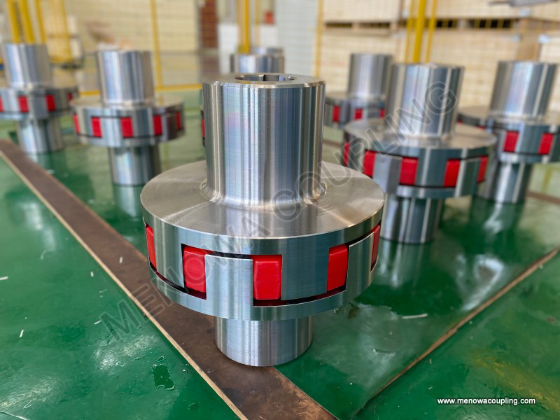
To fully grasp the significance of a gap chart, it is first necessary to understand the fundamental role of elastic couplings in mechanical systems. Elastic couplings are designed to transmit torque from one shaft to another while compensating for three main types of misalignments: radial, angular, and axial. Radial misalignment occurs when the two shafts are parallel but not concentric, resulting in a lateral offset. Angular misalignment happens when the shafts are not parallel, forming an angle between their axes. Axial misalignment refers to the axial displacement of one shaft relative to the other, which can occur due to thermal expansion, vibration, or installation errors. Unlike rigid couplings, which require near-perfect alignment to function properly, elastic couplings use flexible elements—such as rubber, polyurethane, or metal springs—to absorb these misalignments, reduce vibration, and protect the connected equipment, such as motors, pumps, compressors, and gearboxes. However, even with their flexible design, elastic couplings have specific limits to the misalignments they can accommodate, and exceeding these limits can lead to increased wear, reduced efficiency, and eventual failure. This is where the gap chart becomes crucial: it provides a systematic way to measure, record, and monitor the gaps and misalignments, ensuring they remain within the acceptable range.
A gap chart typically includes several key components that collectively provide a comprehensive overview of the coupling’s alignment and condition. The first and most basic component is the identification information, which includes details such as the type of elastic coupling (e.g., jaw coupling, coupling, bellows coupling, or tire coupling), the application it is used in, the date of measurement, the name of the technician performing the measurement, and the equipment identification number. This information is essential for traceability, especially in large industrial facilities with multiple couplings, where maintaining accurate records is critical for scheduled maintenance and troubleshooting. Next, the gap chart includes measurements of the radial gap, which is the distance between the outer surfaces of the two coupling hubs at various points around the circumference. This measurement helps determine the radial misalignment between the shafts. The axial gap, which is the distance between the two coupling faces (or between specific reference points on the coupling), is also recorded to assess axial misalignment and ensure there is sufficient clearance to accommodate thermal expansion and axial movement. Additionally, the gap chart may include angular gap measurements, which are used to quantify the angular misalignment between the shafts by measuring the variation in axial gap at different points around the coupling’s circumference.
Constructing a gap chart requires careful measurement using the appropriate tools and techniques to ensure accuracy. The process typically begins with preparing the equipment: the machine should be shut down, disconnected from power, and allowed to cool to ambient temperature to avoid thermal expansion affecting the measurements. This is particularly important for equipment that operates at high temperatures, as thermal expansion can cause significant changes in shaft alignment. Once the equipment is prepared, the technician selects the appropriate measurement tools. Common tools used for gap measurements include feeler gauges, dial indicators (also known as dial gauges), laser alignment tools, and calipers. Feeler gauges are simple, cost-effective tools used to measure small gaps between two surfaces, making them ideal for measuring axial gaps between coupling faces. Dial indicators, often mounted on a magnetic base or a fixture attached to one of the coupling hubs, are used to measure radial and axial runout, which helps determine misalignments. Laser alignment tools are more advanced, providing highly accurate measurements of radial, angular, and axial misalignments, and are often used in applications where precision is critical, such as in high-speed machinery or precision manufacturing equipment.
The measurement process for constructing a gap chart involves taking multiple readings at different points around the coupling’s circumference to account for any irregularities. For radial gap measurements, the technician typically divides the coupling into four equal quadrants (0°, 90°, 180°, and 270°) and measures the radial distance between the two hubs at each quadrant. These measurements are recorded on the gap chart, and the differences between the maximum and minimum readings are used to calculate the radial misalignment. For axial gap measurements, the same quadrants are used, and the feeler gauge or dial indicator is used to measure the gap between the two coupling faces at each point. The variation in axial gap readings across the quadrants indicates the angular misalignment: if the axial gap is larger at one quadrant and smaller at the opposite quadrant, it indicates an angular misalignment between the shafts. In some cases, additional measurements may be taken at intermediate points (e.g., 45°, 135°, etc.) to ensure accuracy, especially for couplings with larger diameters or in applications where precision is critical.
Once the measurements are taken and recorded, the gap chart is analyzed to determine the alignment status of the coupling and whether any adjustments are needed. The analysis involves comparing the measured gaps and misalignments to the manufacturer’s recommended limits for the specific type of elastic coupling. These limits are based on the coupling’s design, including the material of the flexible element, the size of the coupling, and the intended application. For example, a small jaw coupling used in a light-duty application may have a maximum radial misalignment limit of a few tenths of a millimeter, while a larger tire coupling used in a heavy-duty industrial application may be able to accommodate several millimeters of radial misalignment. If the measured misalignments are within the recommended limits, the coupling is considered properly aligned, and no adjustments are needed. However, if the misalignments exceed the limits, the technician must take corrective action to realign the shafts, which may involve adjusting the position of the motor or driven equipment using shims, adjusting the base plates, or modifying the mounting hardware.
The gap chart also serves as a valuable tool for predictive maintenance, allowing technicians to monitor changes in the coupling’s alignment over time. By comparing gap charts taken at different intervals (e.g., monthly, quarterly, or annually), technicians can identify trends in misalignment, such as a gradual increase in radial or angular misalignment, which may indicate underlying issues such as wear in the bearings, settlement of the equipment base, or loosening of mounting bolts. Catching these issues early can prevent more serious problems, such as excessive vibration, premature wear of the coupling’s flexible element, or damage to the connected equipment. For example, if a gap chart shows a steady increase in radial misalignment over several months, it may indicate that the bearings in the motor or driven equipment are wearing out, and replacing the bearings before they fail can avoid costly downtime and repairs. Additionally, the gap chart can be used to verify the effectiveness of alignment adjustments: after realigning the shafts, a new gap chart is created to ensure that the misalignments have been corrected to within the recommended limits.
It is important to note that the gap chart is not a one-time document but rather a living record that should be updated regularly as part of the equipment’s maintenance program. Each time the coupling is inspected, maintained, or realigned, the new measurements should be added to the gap chart, creating a historical record of the coupling’s performance. This historical data is invaluable for troubleshooting unexpected issues: if a coupling fails prematurely, technicians can review the gap charts to see if there were any signs of misalignment or abnormal wear that were not addressed. Additionally, the historical data can be used to optimize the maintenance schedule, allowing technicians to adjust the frequency of inspections based on the rate of misalignment change. For example, if a coupling in a high-vibration environment shows rapid changes in misalignment, the inspection interval may be shortened to catch issues earlier.
Different types of elastic couplings may require slight variations in the gap chart’s format and measurement techniques, depending on their design and application. For example, jaw couplings, which consist of two hubs with jaws that engage a flexible elastomeric spider, typically require measurements of the gap between the jaws and the spider to ensure proper engagement and avoid excessive wear. Bellows couplings, which use a flexible metal bellows to accommodate misalignments, require precise measurements of the radial and axial gaps to prevent the bellows from being overstressed, which can lead to fatigue failure. Tire couplings, which use a flexible tire-like element to connect the two hubs, may require measurements of the tire’s tension and the gap between the tire and the hubs to ensure optimal performance. Regardless of the type of elastic coupling, the core purpose of the gap chart remains the same: to provide accurate, reliable data on the coupling’s alignment and condition to ensure safe and efficient operation.
In addition to installation and maintenance, the gap chart is also a valuable tool during the design and selection of elastic couplings. Engineers can use gap charts to determine the appropriate type and size of coupling for a specific application by analyzing the expected misalignments and ensuring that the coupling can accommodate them within its design limits. For example, if a system is expected to have significant radial misalignment due to the installation layout, an engineer may select a coupling with a larger radial misalignment capacity, and the gap chart can be used to verify that the selected coupling meets the application’s requirements. Additionally, during the design phase, gap charts can be used to simulate different alignment scenarios and optimize the coupling’s design to improve its performance and longevity.
Common mistakes to avoid when creating and using gap charts include taking measurements when the equipment is still hot, using inaccurate or damaged measurement tools, taking too few measurements around the coupling’s circumference, and failing to record important identification information. Taking measurements when the equipment is hot can lead to incorrect readings due to thermal expansion, which can result in improper alignment and premature coupling failure. Using inaccurate tools, such as a worn feeler gauge or a misaligned dial indicator, can also lead to incorrect measurements, which may result in unnecessary adjustments or missed issues. Taking too few measurements (e.g., only one or two points around the circumference) can fail to capture irregularities in the coupling’s alignment, leading to an incomplete or inaccurate gap chart. Finally, failing to record identification information can make it difficult to trace the gap chart to a specific coupling or equipment, which can hinder troubleshooting and maintenance efforts.
Another important consideration when using gap charts is the impact of environmental factors on the coupling’s alignment. Factors such as temperature changes, humidity, vibration, and dust can all affect the alignment of the shafts and the gaps in the coupling. For example, in outdoor applications, temperature fluctuations can cause the equipment base to expand and contract, leading to changes in shaft alignment. In dusty environments, debris can accumulate between the coupling components, altering the gap measurements and potentially causing wear. Technicians should take these factors into account when interpreting gap chart data and adjust their maintenance practices accordingly. For example, in outdoor applications, more frequent gap measurements may be needed to account for seasonal temperature changes, while in dusty environments, regular cleaning of the coupling components may be necessary to ensure accurate gap measurements.
The role of the gap chart in ensuring the reliability and efficiency of elastic couplings cannot be overstated. In industrial applications, where downtime can be costly and equipment failure can lead to safety hazards, having accurate and up-to-date gap charts is essential for maintaining optimal performance. By providing a systematic way to measure, record, and monitor the coupling’s alignment and condition, the gap chart helps technicians identify potential issues early, avoid premature failure, and extend the service life of the coupling and the connected equipment. Additionally, the gap chart serves as a valuable training tool for new technicians, helping them understand the importance of alignment and how to properly measure and interpret gap data.
In conclusion, the gap chart of elastic coupling is a critical technical document that plays a vital role in the installation, alignment, maintenance, and troubleshooting of elastic couplings. It provides precise measurements of the gaps and misalignments between the coupling components and connected shafts, allowing technicians to ensure the coupling operates within its design limits. By following proper measurement techniques, maintaining accurate records, and regularly updating the gap chart, engineers and technicians can optimize the performance and longevity of elastic couplings, reduce downtime, and ensure the safe and efficient operation of mechanical systems. Whether used in light-duty applications such as small motors and pumps or heavy-duty industrial applications such as compressors and gearboxes, the gap chart remains an indispensable tool for anyone working with elastic couplings.
Post Date: May 14, 2026
https://www.menowacoupling.com/china-coupling/gap-chart-of-elastic-coupling.html
Products

Related Articles
Size Chart of Elastic Coupling
The size chart of elastic coupling is an indispensable reference tool in mechanical transmission systems, serving as a bridge between the coupling’s design parameters and its practical application. It systematically organizes key dimensional and performance data, enabling engineers, technicians, and procurement personn…Structure of Elastic Coupling
An elastic coupling is a critical mechanical component designed to connect two rotating shafts—typically a driving shaft and a driven shaft—in various mechanical systems, enabling the seamless transmission of torque while accommodating misalignments and dampening vibrations. Unlike rigid couplings that require precise…Elastic Coupling For Sale
In the complex world of mechanical transmission systems, elastic couplings stand as essential components that bridge the gap between rotating shafts, ensuring smooth power transfer while accommodating the inevitable misalignments and vibrations that occur during operation. These versatile devices are designed to transmi…Diagram of Elastic Coupling
Diagram of Elastic CouplingAn elastic coupling is a critical mechanical component designed to connect two rotating shafts, transmitting torque while accommodating misalignments, absorbing vibrations, and mitigating shock loads in various industrial and mechanical systems. Unlike rigid couplings that require precise alig…Elastic Coupling Production
Elastic couplings are essential components in mechanical transmission systems, serving as the critical link between two rotating shafts to transmit torque while accommodating misalignments, absorbing vibrations, and reducing shock loads. The production of elastic couplings is a sophisticated process that combines precis…Characteristics of Elastic Coupling
Elastic coupling is a critical component in mechanical transmission systems, designed to connect two rotating shafts while accommodating various forms of misalignment, absorbing vibrations, and transmitting torque efficiently. Unlike rigid couplings that require precise alignment and offer no flexibility, elastic coupli…Working Principle of Elastic Coupling
In the complex and interconnected world of mechanical power transmission, elastic couplings stand as indispensable components that bridge the gap between driving and driven shafts, ensuring the smooth, efficient, and protected transfer of torque. Unlike rigid couplings that demand precise alignment and offer no flexibil…Uses of Elastic Coupling
In the complex landscape of mechanical power transmission, elastic couplings stand as indispensable components that bridge the gap between rotating shafts, ensuring seamless torque transfer while addressing the inherent challenges of misalignment, vibration, and shock. Unlike rigid couplings that demand precise alignmen…Classification of Elastic Coupling
Elastic couplings are essential mechanical components designed to connect two rotating shafts while transmitting power efficiently, compensating for misalignments, and dampening vibrations and shock loads. Unlike rigid couplings, which require near-perfect alignment between shafts and offer no flexibility, elastic coupl…Components of Elastic Coupling
Elastic couplings are essential mechanical components widely used in various industrial applications to connect two rotating shafts, transmitting torque while accommodating misalignments, absorbing vibrations, and protecting connected equipment from damage. Unlike rigid couplings that require precise alignment and offer…
 WeChat
 WhatsApp