Gap Chart of Gear Type Coupling
Gear type couplings stand as one of the most widely used mechanical transmission components in industrial power systems, relied upon for their exceptional torque transmission capacity, high structural rigidity, and reliable adaptability to complex operating conditions. At the core of their stable operation lies the precise control of meshing gaps between internal and external gear teeth, a key dimensional parameter that directly determines the coupling’s misalignment compensation capability, transmission efficiency, service life, and operational stability. A comprehensive gap chart serves as a standardized reference framework that quantifies the reasonable gap range of gear type couplings under different structural specifications, operating speeds, load conditions, and misalignment states, providing critical guidance for product design, assembly debugging, daily operation maintenance, and fault diagnosis. Unlike fixed structural dimensions, the gap values of gear type couplings are not static figures but dynamic variable ranges that change with multiple influencing factors, making the in-depth interpretation and application of gap charts essential for maximizing the working performance of gear coupling systems.
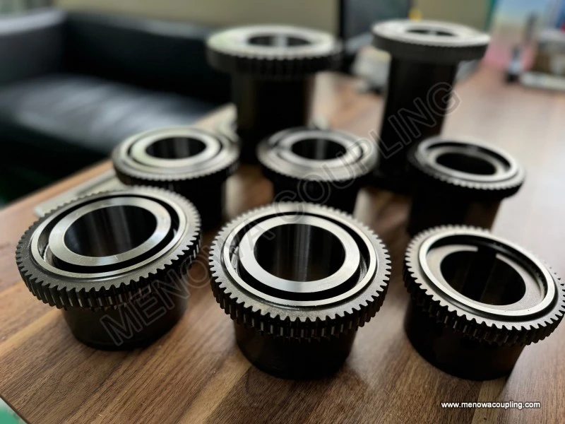
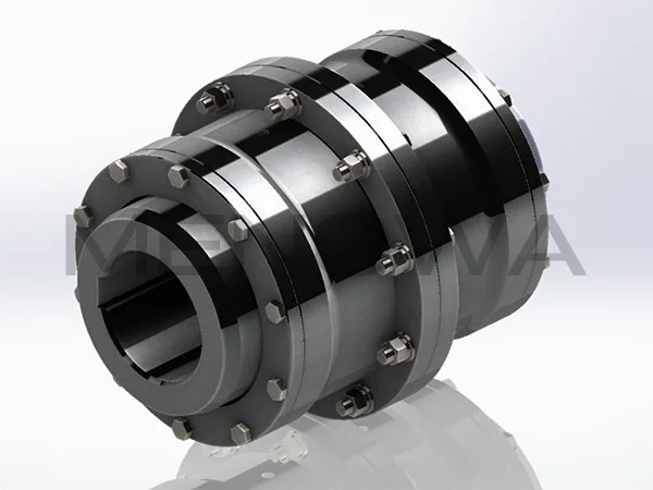
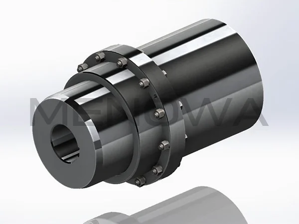
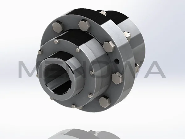
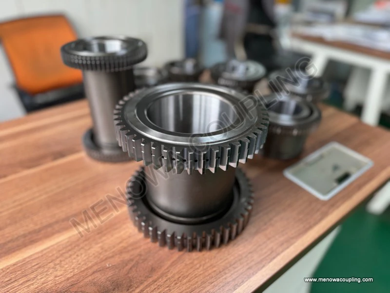
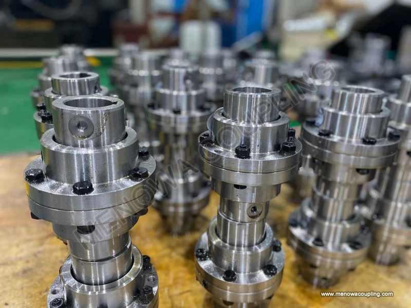
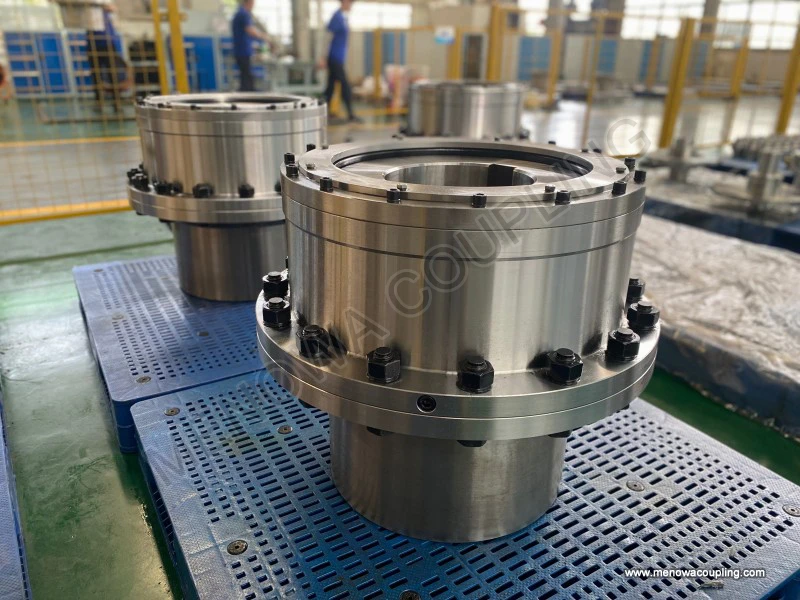
To understand the practical value of the gear type coupling gap chart, it is first necessary to clarify the structural source and functional significance of coupling gaps. A standard gear type coupling is mainly composed of two external gear hubs and an internal gear sleeve, with power transmission realized through the meshing fit between the external teeth of the hubs and the internal teeth of the sleeve. To enable the coupling to compensate for the inevitable relative displacement of the connected shafts during operation—including axial displacement, radial parallel offset, and angular deflection—a reserved meshing gap is intentionally designed between the matching tooth surfaces. This gap is the core parameter recorded and analyzed in the gap chart. The existence of a reasonable gap allows relative sliding and slight pivoting between internal and external gear teeth during shaft misalignment, avoiding rigid extrusion and friction between tooth surfaces, while eliminating transmission jitter and torque loss caused by shaft position deviation. Conversely, unreasonable gap values, whether excessive or insufficient, will trigger a series of operational failures and performance degradation problems, which is why the gap chart has become an indispensable technical basis for industrial application of gear couplings.
The gap chart of gear type couplings systematically sorts out the standard gap ranges corresponding to different coupling specifications and operating scenarios, with gap classification divided according to structural form, tooth profile design, and working state. Structurally, gear type couplings are divided into full gear couplings and half gear couplings, and their gap standards show obvious differences. Full gear couplings adopt a double-sided meshing structure with two flexible gear hubs, featuring two flexible working planes, which requires a relatively uniform gap distribution on both sides of the tooth profile to ensure balanced misalignment compensation in all directions. The gap values specified in the chart for this structure are moderately reserved to adapt to simultaneous angular and radial misalignment. In contrast, half gear couplings adopt a single flexible and single rigid matching structure, with only one set of meshing teeth undertaking displacement compensation, so the standard gap range in the chart is slightly concentrated, focusing on adapting to axial and small-range radial displacement, and the gap tolerance is relatively stricter to avoid unilateral stress concentration. In terms of tooth profile design, straight-tooth gear couplings and crowned-tooth gear couplings also differ significantly in gap parameters. Crowned-tooth couplings adopt curved spherical tooth profile processing, which eliminates edge contact of tooth surfaces under misalignment conditions, so the standard gap range in the chart is relatively wider than that of straight-tooth structures, allowing larger shaft displacement while maintaining uniform tooth surface contact.
The core data dimension of the gear type coupling gap chart covers static assembly gaps and dynamic operating gaps, two key working states that must be strictly distinguished in practical application. Static assembly gap refers to the tooth surface meshing gap measured when the coupling is in a stationary, no-load, and perfectly aligned state, which is the basic calibration data of the gap chart. This gap is mainly determined by machining tolerance and assembly accuracy, with a fixed standard range for each coupling specification. The static gap ensures smooth assembly of internal and external gears, avoids assembly jamming caused by dimensional deviation, and reserves the basic space for subsequent dynamic displacement compensation. Dynamic operating gap, as the core application data of the gap chart, refers to the real-time meshing gap of gear teeth under working conditions with load operation, shaft misalignment, and mechanical vibration. Affected by load torque, operating speed, shaft displacement, and component thermal deformation, the dynamic gap will fluctuate dynamically on the basis of the static gap. The gap chart clearly marks the allowable fluctuation range of dynamic gaps under different working loads and speeds, providing a judgment basis for distinguishing normal gap fluctuation and abnormal gap failure.
In actual industrial operation, the dynamic gap of gear type couplings is affected by multiple external factors, and the gap chart summarizes the corresponding gap change rules under different working conditions, forming a complete parameter adaptation system. Load change is the most intuitive influencing factor. Under light-load working conditions, the gear teeth bear small pressure, the tooth surface deformation is negligible, and the dynamic gap is basically consistent with the static gap standard specified in the chart. With the gradual increase of transmission torque, the gear teeth produce slight elastic deformation under pressure, the meshing contact area increases, and the effective gap decreases slightly. The gap chart records the reasonable gap attenuation range under medium and heavy loads, defining the minimum allowable gap to prevent tooth surface extrusion wear caused by excessive load compression. Operating speed is another key influencing factor. In low-speed operation, the coupling runs stably with weak vibration, and the gap fluctuation amplitude is small. In high-speed rotating states, the centrifugal force of components and system vibration will cause tiny relative displacement between meshing teeth, leading to a slight increase in dynamic gap. The gap chart formulates graded gap tolerance standards according to different speed ranges, ensuring that the gap fluctuation does not affect transmission stability during high-speed operation.
Shaft misalignment state is the core factor that makes the gap chart have practical guiding significance, and it is also the fundamental reason for the functional design of coupling gaps. The gap chart quantifies the optimal gap range corresponding to axial, radial, and angular misalignment respectively, forming a targeted parameter matching rule. When axial misalignment occurs between the connected shafts, the internal and external gear teeth produce axial relative sliding, and the gap along the shaft direction provides a sliding space. The gap chart specifies the corresponding gap increment range under different axial displacement distances to ensure unobstructed axial sliding without tooth surface clamping. For radial parallel misalignment, the offset of the shaft center will cause uneven meshing gaps on both sides of the gear teeth. The standard gap range in the chart can balance the unilateral pressure caused by radial offset, avoiding partial excessive wear of individual tooth surfaces. In terms of angular misalignment, which is the most common working state, the inclined shaft state makes the gear teeth produce angular deflection meshing. The gap chart matches the gradient gap standard according to the deflection angle, ensuring full contact of the tooth surface middle section and avoiding edge stress concentration, which is the key to preventing early tooth surface fatigue damage.
Temperature variation in the working environment also brings dynamic changes to the coupling gap, and the gap chart supplements the gap correction parameters for temperature factors. During long-term continuous operation, the friction of gear meshing and the heat generated by system operation will cause thermal expansion of coupling metal components. The tooth thickness of internal and external gears increases slightly after thermal expansion, resulting in a reduction in meshing gaps. In high-temperature working environments such as metallurgy, chemical industry, and thermal power, the thermal deformation of components is more obvious. The gap chart formulates low-temperature reserved gaps and high-temperature correction gaps for different ambient temperature ranges, ensuring that the coupling still maintains a reasonable meshing gap after thermal expansion, avoiding tooth surface biting and dry friction caused by excessive gap reduction. At the same time, for low-temperature working environments, the chart also appropriately expands the allowable gap fluctuation range, preventing component cold shrinkage from causing excessive gap and abnormal transmission impact.
Analyzing the abnormal gap ranges recorded in the gear type coupling gap chart is of great significance for equipment fault diagnosis and early warning. The chart clearly defines the critical threshold of abnormal gaps, and once the actual operating gap exceeds the standard range, it corresponds to specific potential faults. When the gap is lower than the minimum standard value for a long time, the meshing of internal and external gear teeth is too tight, the friction resistance during operation increases significantly, the tooth surface is prone to abrasive wear and gluing failure, and the operating temperature of the coupling rises abnormally, which will accelerate the fatigue aging of components and even cause shaft jamming in severe cases. This abnormal tight gap state is usually caused by excessive assembly precision, insufficient reserved static gap, or excessive thermal deformation under long-term high-load operation. When the gap is higher than the maximum standard value, excessive meshing clearance will be formed between gear teeth. During torque transmission, the gap will cause periodic impact and jitter of meshing teeth, resulting in unstable transmission, increased system vibration and noise, and easy fatigue fracture of gear teeth under repeated impact load. Excessive gaps are mostly caused by long-term wear of tooth surfaces, loose assembly of coupling components, or excessive shaft misalignment beyond the compensation range.
The gap chart also provides standardized guidance for coupling assembly and daily maintenance, realizing the whole-process control of gap parameters. In the assembly stage, workers can calibrate the static meshing gap according to the standard data in the chart, adjust the assembly position of the gear hub and sleeve, and control the static gap within the optimal range, laying a foundation for stable dynamic operation. For newly assembled couplings, the gap tolerance is strictly controlled at the middle value of the standard range to leave sufficient fluctuation space for subsequent load operation and thermal deformation. In daily maintenance, the operating gap can be measured regularly through professional detection tools, and the measured data can be compared with the dynamic gap standard in the chart. When the gap fluctuates within the allowable range, it indicates that the coupling operates normally; when the gap gradually increases or decreases and approaches the critical threshold, targeted maintenance measures such as adjusting shaft alignment, cleaning lubricating oil dirt, or checking component wear can be taken in advance to avoid sudden equipment failure.
Lubrication conditions, though not directly marked as gap data in the chart, are important auxiliary factors affecting the effective utilization of coupling gaps, and the gap chart’s applicable scenarios are matched with standardized lubrication requirements. A reasonable meshing gap needs to be filled with lubricating oil to form a uniform oil film on the tooth surface, which isolates metal contact, reduces friction and wear, and buffers meshing impact. If the gap is too small, the lubricating oil film cannot be effectively formed and stored, resulting in poor lubrication effect and dry friction of tooth surfaces; if the gap is too large, the lubricating oil is easy to lose, the oil film thickness is uneven, and the buffering and lubricating effect is weakened. The gap chart’s standard gap range is formulated based on the optimal lubrication state, matching the oil film thickness required for normal meshing of gear teeth. Therefore, in practical application, maintaining normal lubrication conditions while controlling the gap within the standard range is the key to giving full play to the coupling’s transmission performance and extending its service life.
In industrial system operation, the long-term stability of gear type couplings depends on the dynamic matching between actual gaps and chart standards. With the extension of service time, the tooth surface will produce inevitable wear, which will gradually increase the meshing gap. The gap chart marks the gap wear threshold of couplings in different service cycles, helping equipment managers judge the service state of couplings. When the gap wear is within the chart’s allowable range, it belongs to normal mechanical wear and does not affect operating performance; when the wear exceeds the threshold, it indicates that the tooth surface wear is excessive, and the coupling needs to be repaired or replaced in time to prevent transmission failure caused by excessive gap impact. This standardized gap management mode based on the gap chart effectively reduces the failure rate of transmission systems and improves the overall operational efficiency and stability of industrial equipment.
In conclusion, the gap chart of gear type couplings is a systematic and standardized parameter guide covering design, assembly, operation, maintenance, and fault diagnosis. It quantifies the complex dynamic gap changes of gear coupling meshing transmission, clarifies the reasonable gap range and abnormal judgment standards under different structural forms, working loads, operating speeds, misalignment states, and temperature conditions. Mastering the application rules of the gap chart can effectively solve the common problems of unstable transmission, rapid component wear, and frequent faults caused by unreasonable gaps in the operation of gear type couplings. In modern industrial mechanical transmission systems, standardized gap management based on professional gap charts has become an important guarantee for the long-term stable and efficient operation of gear coupling equipment, providing solid technical support for the safe operation of various mechanical power transmission systems.
Post Date: May 25, 2026
https://www.menowacoupling.com/china-coupling/gap-chart-of-gear-type-coupling.html
Products
Tags
Supply
Related Articles
Diagram of Curved Tooth Coupling
The diagram of curved tooth coupling intuitively presents the structural layout, meshing logic and spatial assembly relationship of this mainstream flexible transmission component, serving as a core technical reference for design optimization, model selection, installation and maintenance in the global industrial machin…Gear Type Coupling Factory
Gear type couplings stand as one of the most reliable and widely adopted power transmission components in modern industrial mechanical systems, serving as a critical bridge between rotating shafts in diverse heavy-duty and high-precision equipment. As a professional gear type coupling manufacturing facility, we focus on…Material of Gear Type Coupling
Gear type couplings stand as one of the most reliable and widely adopted power transmission components in modern mechanical systems, renowned for their high torque transmission capacity, compact structural design, and excellent tolerance to shaft misalignment. The overall performance, service lifespan, and operational s…Diagram of Gear Type Coupling
A gear type coupling is a crucial mechanical component widely utilized in industrial transmission systems to connect two rotating shafts, enabling the efficient transfer of torque while accommodating minor misalignments that may occur during operation. Unlike rigid couplings that require precise alignment between shafts…Gear Type Coupling For Sale
A gear type coupling is a versatile and robust mechanical device designed to connect two rotating shafts, enabling the efficient transmission of torque while accommodating a certain degree of misalignment between the shafts. This type of coupling is widely recognized for its ability to handle heavy loads and harsh opera…Dimensions of Curved Tooth Coupling
Global industrial development across diversified manufacturing sectors continues to push steady market expansion for curved tooth couplings, whose unique curved crowned tooth geometry distinguishes them from conventional straight-tooth gear couplings and enables outstanding comprehensive mechanical performance to match …
 WeChat
 WhatsApp