Dimensions of Gear Type Coupling
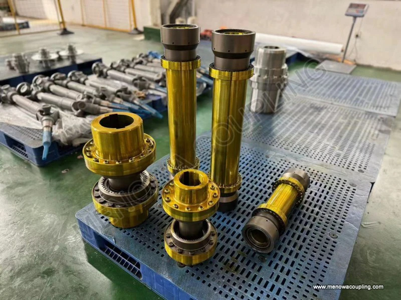
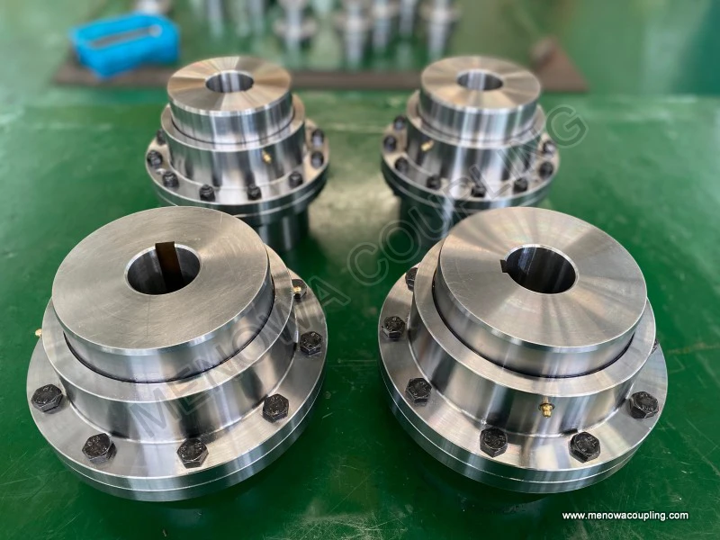
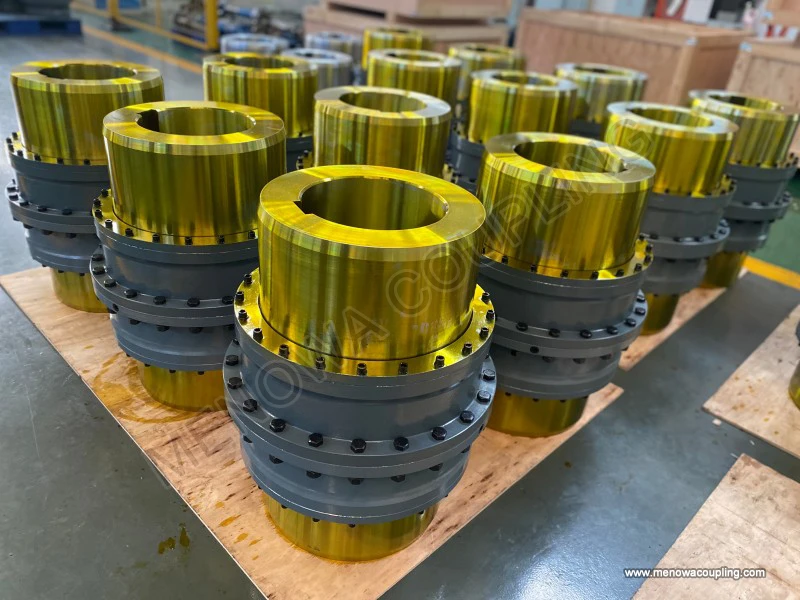
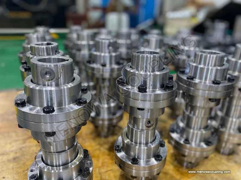
Gear type couplings stand as fundamental flexible transmission components widely applied in industrial mechanical systems, primarily tasked with transmitting rotational torque between adjacent drive and driven shafts while accommodating minor shaft misalignments generated by mechanical operation, assembly errors, and structural deformation. The dimensional parameters of gear type couplings serve as the core foundation determining their transmission performance, operational stability, service life, and application adaptability. Unlike rigid coupling structures, the dimensional design of gear type couplings involves coordinated optimization of multiple structural parts, including external gear hubs, internal gear sleeves, gear teeth profiles, and assembly clearances. Every dimensional indicator is closely linked to torque bearing capacity, rotational speed adaptability, misalignment compensation range, and mechanical operation safety, making in-depth exploration of its dimensional characteristics and design logic essential for mechanical selection, structural design, and equipment maintenance.
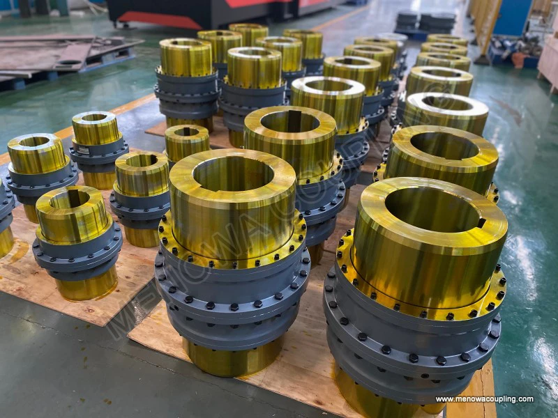
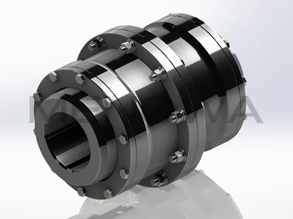
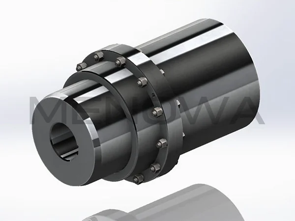
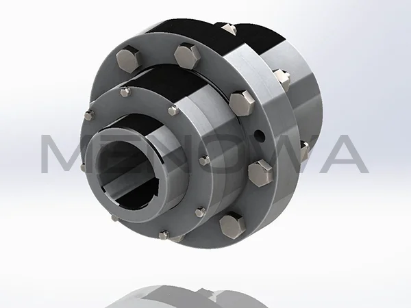
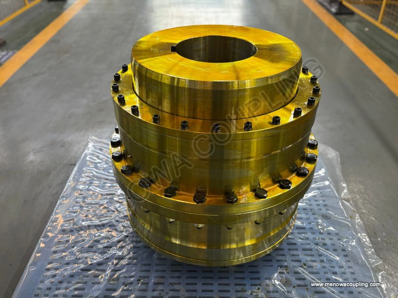
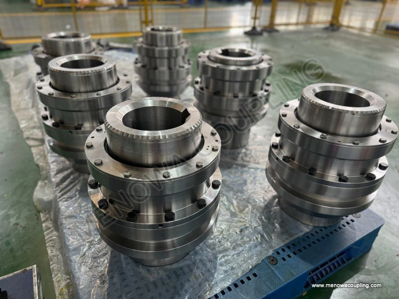
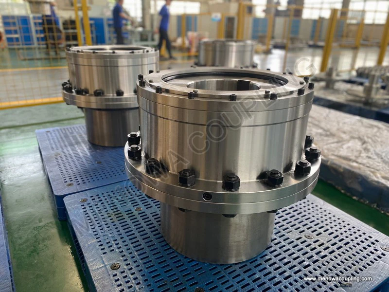
The basic dimensional composition of a standard gear type coupling mainly covers overall external dimensions, shaft hole matching dimensions, gear tooth structural dimensions, and internal assembly clearance dimensions. The overall external dimensions include the maximum outer diameter of the coupling sleeve and the total assembly length of the entire coupling set. These two macroscopic dimensions directly determine the spatial occupancy of the coupling in mechanical equipment, which is a key indicator for preliminary model selection in limited installation spaces. In compact mechanical structures such as precision transmission equipment and modular industrial machinery, oversized outer diameter and assembly length will cause structural interference with surrounding parts, increase the overall volume of the equipment, and even affect the layout of transmission components. Conversely, excessively small overall dimensions will lead to insufficient structural rigidity, making the coupling prone to elastic deformation and structural fatigue under high-load operation, thereby reducing transmission efficiency and service stability.
Shaft hole dimensional parameters are the most critical matching indicators for the connection between gear type couplings and transmission shafts, mainly including shaft hole diameter, shaft hole depth, and keyway size. The shaft hole diameter must form a precise fit with the outer diameter of the mating shaft. A reasonable fit tolerance ensures synchronous rotation of the coupling and the shaft without relative sliding, while avoiding assembly difficulties caused by excessive interference or transmission vibration caused by excessive clearance. The shaft hole depth is designed according to the shaft extension length of the equipment, ensuring sufficient assembly engagement length to guarantee torque transmission uniformity. Insufficient shaft hole depth will result in insufficient contact area between the coupling and the shaft, leading to local stress concentration and shaft wear during high-torque operation, while excessive depth will cause redundant structural space and increase unnecessary structural weight. The keyway dimensions, including width, depth, and groove length, cooperate with flat keys or splines to realize torque transmission, and their dimensional accuracy directly affects the uniformity of force bearing during power transmission, preventing torque loss and component abrasion caused by key loosening or extrusion deformation.
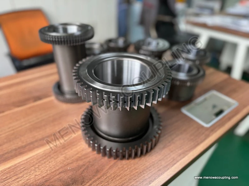
Gear tooth structural dimensions constitute the core functional dimensions of gear type couplings, determining the load-bearing capacity and misalignment compensation performance of the equipment. This series of dimensions involves gear module, tooth number, tooth width, tooth profile height, and tooth surface roughness. The gear module is the basic parameter that determines the size and bearing capacity of a single gear tooth. A larger module means thicker and stronger gear teeth, which can bear greater torque load and adapt to heavy-duty industrial transmission scenarios. The tooth number affects the meshing uniformity and stability of the coupling. An appropriate number of teeth can ensure multi-tooth synchronous meshing, disperse transmission load, and reduce vibration and noise during operation. Too few teeth will cause discontinuous meshing and unstable torque transmission, while too many teeth will reduce the single-tooth bearing area and weaken the overall load capacity of the coupling.
Tooth width is a key dimension affecting the contact area of gear meshing. Within a reasonable range, increasing tooth width can expand the meshing contact area, improve torque transmission efficiency, and reduce unit pressure on the tooth surface, thus slowing down tooth surface wear and extending service life. However, excessive tooth width will increase the axial dimensional span of the coupling, reduce the structural flexibility of the gear teeth, and weaken the coupling’s ability to compensate for angular misalignment. The tooth profile height parameters, including addendum height and dedendum height, determine the meshing depth and meshing clearance of internal and external gears. Reasonable tooth profile height dimensions can ensure full meshing of gear teeth while avoiding meshing jamming and tooth top interference during high-speed rotation and misalignment adjustment. The matching dimensional tolerance of tooth profiles also plays a vital role in operation stability; precise dimensional matching ensures uniform meshing clearance of each gear tooth and avoids local over-wear caused by uneven force distribution.
Internal assembly clearance dimensions are easily overlooked but essential dimensional indicators for the normal operation of gear type couplings, mainly including radial clearance and axial clearance between internal and external gear pairs. Radial clearance provides space for the coupling to compensate for radial misalignment of the shaft, preventing rigid friction and collision between internal and external gear sleeves during shaft offset. Axial clearance adapts to axial displacement of the shaft caused by thermal expansion and mechanical vibration during equipment operation, eliminating axial extrusion stress between components. The setting of clearance dimensions needs to balance flexibility and stability: excessive clearance will cause large operational vibration and torque fluctuation, affecting transmission precision; too small clearance will lead to poor misalignment compensation ability, and friction and wear will intensify after equipment thermal expansion, seriously affecting the service life of the coupling.
The dimensional design and selection of gear type couplings are not fixed but need to be dynamically adjusted according to actual working conditions, with load characteristics, rotational speed, and misalignment degree being the three core influencing factors. In heavy-load and low-speed transmission scenarios such as mining machinery and metallurgical equipment, the dimensional design focuses on improving structural rigidity and load-bearing capacity. It is necessary to appropriately increase the gear module, tooth width, and wall thickness of the gear sleeve, expand the shaft hole matching area, and reduce assembly clearance within a reasonable range to ensure stable bearing of large torque loads and avoid structural deformation and tooth surface failure. In high-speed and light-load scenarios such as precision machine tool transmission and fan equipment, the dimensional design prioritizes operational stability and dynamic balance accuracy. The overall outer diameter and rotational inertia need to be controlled, gear tooth dimensional accuracy and uniformity need to be improved, and assembly clearance needs to be optimized to reduce high-speed vibration, noise, and centrifugal force loss.
Shaft misalignment status in actual operation also restricts the dimensional design of gear type couplings. In mechanical systems with large assembly errors or easy structural deformation, the coupling needs a larger misalignment compensation range, which requires appropriately increasing the meshing clearance of gear teeth and reserving sufficient flexible adjustment space in axial and radial dimensions. Correspondingly, the overall structural dimensions will be slightly increased, and the gear tooth flexibility will be optimized to adapt to frequent misalignment adjustment. In precision transmission systems with strict requirements on shaft alignment, the dimensional tolerance of each component needs to be strictly controlled, the assembly clearance is minimized, and the matching precision of shaft holes and gear teeth is improved to ensure high-precision and low-jitter power transmission.
Material characteristics also have a indirect guiding effect on the dimensional design of gear type couplings. Different structural materials have differences in strength, hardness, toughness, and thermal expansion coefficient, which require adaptive adjustment of dimensional parameters. For high-strength alloy materials with good rigidity and wear resistance, the structural dimensions can be appropriately optimized and streamlined on the premise of meeting load requirements, reducing the overall weight of the coupling and improving dynamic response speed. For conventional carbon steel materials with relatively general comprehensive performance, it is necessary to increase the structural size of key load-bearing parts such as gear teeth and hub walls to make up for the insufficient material strength and ensure the overall structural stability of the coupling. In addition, considering the thermal expansion effect of materials during long-term operation, the cold-state assembly dimensions need to reserve a reasonable thermal deformation allowance to prevent component jamming and excessive friction caused by thermal expansion and dimensional changes after equipment heating.
The coordination of multi-dimensional parameters determines the comprehensive performance of gear type couplings, and single-dimensional pursuit of optimization cannot achieve the best operating effect. For example, simply increasing gear module to improve load capacity will lead to increased gear tooth volume and coupling weight, which may cause excessive centrifugal force during high-speed operation and affect dynamic balance performance. Simply reducing assembly clearance to improve transmission precision will weaken the misalignment compensation ability, making the coupling unable to adapt to slight shaft deformation in complex working conditions. Therefore, dimensional design must follow the principle of balanced coordination, comprehensively considering the mutual restriction and matching relationship between overall dimensions, matching dimensions, core functional dimensions, and clearance dimensions, and carry out targeted optimization according to the priority requirements of actual working conditions.
In the process of equipment maintenance and coupling replacement, the accurate verification of dimensional parameters is also the key to ensuring consistent equipment performance. Replaced couplings must be completely consistent with the original equipment in terms of shaft hole diameter, keyway size, assembly length, and outer diameter to ensure accurate installation and in-place matching. The deviation of gear tooth dimensions and clearance parameters should be controlled within a reasonable tolerance range to avoid changes in transmission performance and compensation ability caused by dimensional differences. For equipment that has been operated for a long time, the wear of coupling key dimensions should be regularly detected, including the wear of gear tooth surfaces, the expansion of shaft hole clearance, and the change of assembly gap. Timely replacement and adjustment should be carried out when the dimensional deviation exceeds the standard range to eliminate potential operational failures.
With the continuous upgrading of modern industrial mechanical systems towards high precision, high efficiency, and lightweight, the dimensional design of gear type couplings is also constantly optimized and innovated. Traditional dimensional design mostly adopts empirical standard matching, while modern design methods combine mechanical simulation and finite element analysis to carry out refined dimensional optimization. By simulating the stress distribution, deformation state, and dynamic operation of the coupling under different load and speed conditions, the redundant structural dimensions are reduced, the weak links of dimensional bearing are strengthened, and the dimensional matching precision of each component is improved. This refined dimensional design not only ensures the high load-bearing and stable transmission performance of the coupling but also realizes the lightweight and compact design of the structure, which is more suitable for the development needs of modern modular and integrated mechanical equipment.
In summary, the dimensional system of gear type couplings is a systematic and integrated design system covering macroscopic overall size, matching connection size, core functional structure size, and assembly gap size. All dimensional parameters are interrelated and restricted, jointly determining the transmission performance, adaptability, and service reliability of the coupling. In mechanical design, equipment selection, and daily maintenance, accurate grasp of the dimensional characteristics of gear type couplings and their adaptation rules to working conditions is crucial to giving full play to the performance advantages of gear couplings, ensuring the long-term stable operation of mechanical transmission systems, and reducing equipment failure rates and maintenance costs. The continuous optimization of dimensional design will also further expand the application scope of gear type couplings and meet the increasingly diverse and high-standard industrial transmission needs.
Post Date: May 25, 2026
https://www.menowacoupling.com/china-coupling/dimensions-of-gear-type-coupling.html
Products
Tags
Supply
Related Articles
Size Chart of Curved Tooth Coupling
The global industrial transmission component market has maintained steady expansion alongside the continuous upgrading of industrial manufacturing, intelligent equipment iteration, and the vigorous development of heavy industry sectors worldwide. As a core high-efficiency power transmission component, curved tooth coupl…Coaxiality of Curved Tooth Coupling
In the global industrial transmission industry, curved tooth couplings have emerged as a core component of high-precision and high-torque shaft connection systems, widely adopted in heavy machinery, automated production lines, energy transmission equipment and cross-border industrial supporting fields. Coaxiality, as th…What is Gear Type Coupling
Gear type coupling is a fundamental flexible mechanical transmission component widely applied in modern industrial power transmission systems, serving as a critical connecting unit between two rotating shafts in mechanical equipment. Unlike rigid couplings that require precise shaft alignment and lack displacement compe…Gap Chart of Gear Type Coupling
Gear type couplings stand as one of the most widely used mechanical transmission components in industrial power systems, relied upon for their exceptional torque transmission capacity, high structural rigidity, and reliable adaptability to complex operating conditions. At the core of their stable operation lies the prec…Size Chart of Gear Type Coupling
A size chart of gear type coupling is an indispensable reference tool in industrial power transmission systems, serving as a bridge between the functional requirements of machinery and the technical specifications of the coupling itself. It systematically organizes key dimensional and performance parameters, allowing en…Barrel Gear Coupling Hubs
Barrel gear coupling hubs stand as indispensable foundational mechanical components within modern power transmission systems, serving as the key connecting medium that links driving shafts and driven shafts to achieve stable torque transfer, rotational motion synchronization, and effective compensation for various shaft…
 WeChat
 WhatsApp