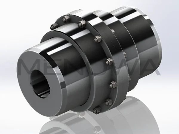
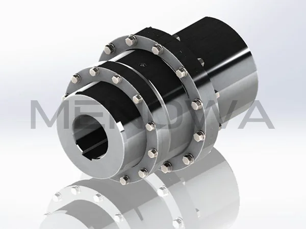
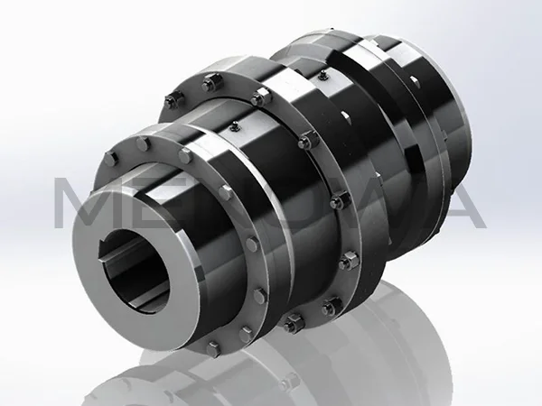
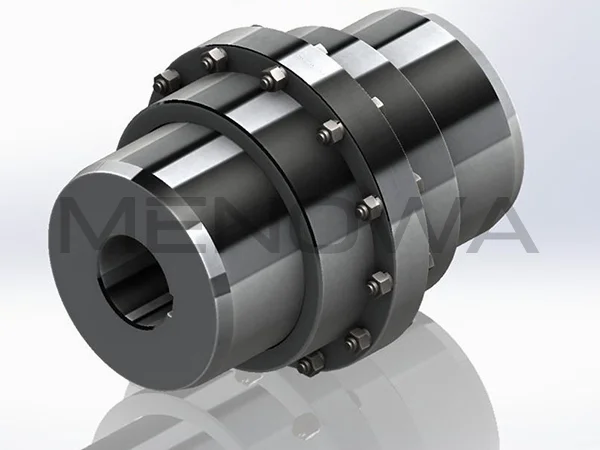
Diagram of Gear Type Coupling
A gear type coupling is a crucial mechanical component widely utilized in industrial transmission systems to connect two rotating shafts, enabling the efficient transfer of torque while accommodating minor misalignments that may occur during operation. Unlike rigid couplings that require precise alignment between shafts, gear type couplings offer a degree of flexibility, making them indispensable in various heavy-duty and high-torque applications across industries such as metallurgy, mining, power generation, and manufacturing. To fully understand the functionality and design of a gear type coupling, it is essential to examine its structural components, working principles, types, installation procedures, maintenance requirements, and practical applications, all of which contribute to its role as a reliable and efficient connection device in mechanical systems.
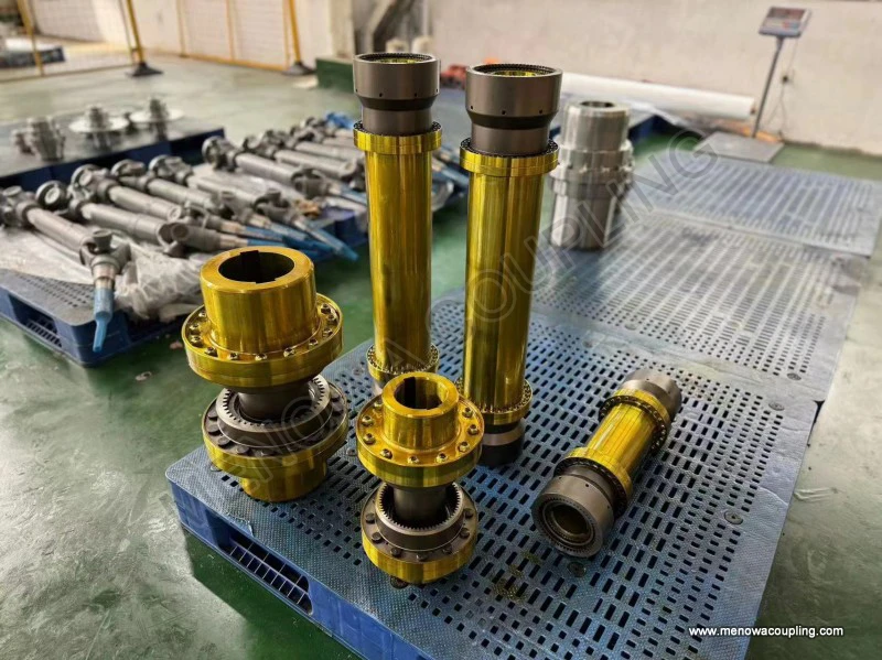
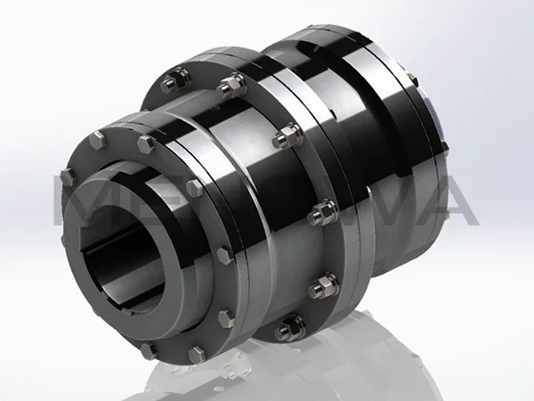
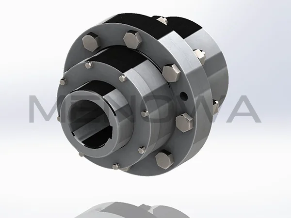
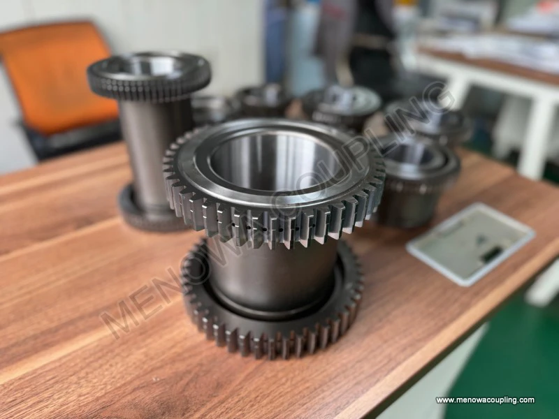
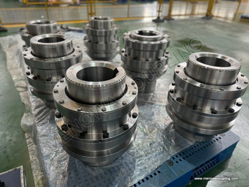
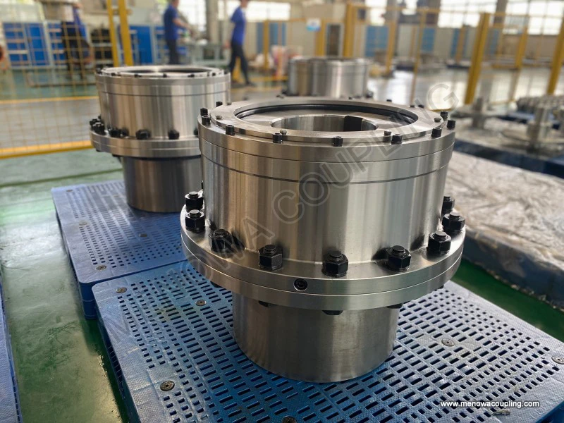
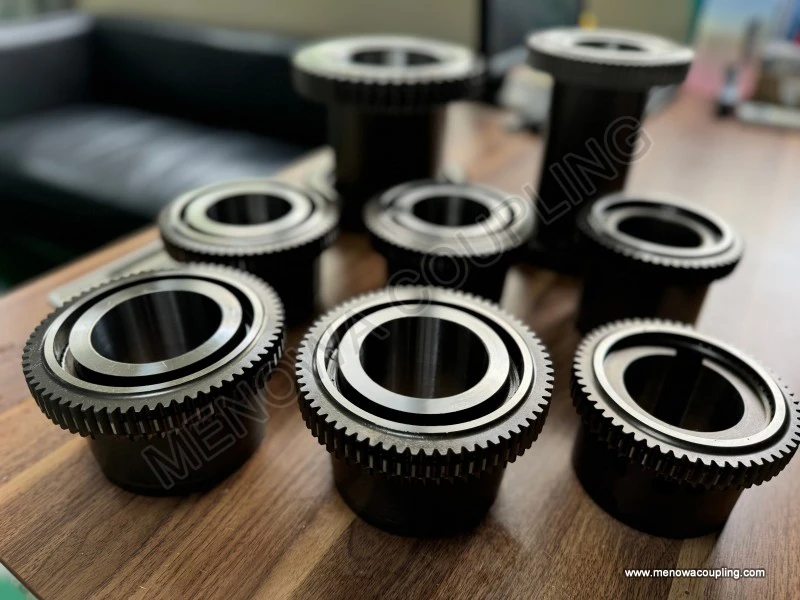
At its core, a gear type coupling consists of several key components that work together to transmit torque and compensate for misalignments. The primary parts include two gear hubs (also known as outer gear sleeves), an inner gear sleeve (or coupling sleeve), end covers, seals, and fasteners such as bolts. Each component plays a specific role in ensuring the coupling’s performance and durability. The gear hubs are typically mounted on the ends of the two shafts that need to be connected, with external gear teeth machined on their outer surfaces. These external teeth are designed to mesh precisely with the internal gear teeth of the inner gear sleeve, creating a secure and efficient torque transfer mechanism. The inner gear sleeve, which encloses the gear hubs, serves as the main torque-transmitting element, while the end covers and seals prevent the entry of contaminants such as dust, dirt, and moisture, which can cause wear and damage to the gear teeth. Additionally, the seals help retain lubrication, which is critical for reducing friction between the meshing gears and extending the coupling’s service life.
The working principle of a gear type coupling is based on the meshing of gear teeth to transfer rotational motion and torque from one shaft to another. When the driving shaft rotates, it turns the gear hub attached to it, which in turn drives the inner gear sleeve through the meshing of external and internal gear teeth. The inner gear sleeve then transmits this rotational motion to the second gear hub, which is connected to the driven shaft, thereby rotating the driven shaft at the same speed (or a speed determined by the gear ratio, though most gear couplings are designed with a 1:1 ratio for direct torque transfer). What sets gear type couplings apart from other coupling types is their ability to compensate for three types of misalignments: angular misalignment, parallel misalignment, and axial misalignment. Angular misalignment occurs when the two shafts are not perfectly collinear and form a slight angle with each other. Parallel misalignment happens when the shafts are parallel but offset from each other, while axial misalignment refers to the axial movement of one shaft relative to the other. The gear teeth design, particularly the use of crowned or drum-shaped teeth in many modern couplings, allows for these misalignments by providing a larger contact area and enabling slight movement between the meshing teeth without compromising torque transfer efficiency.
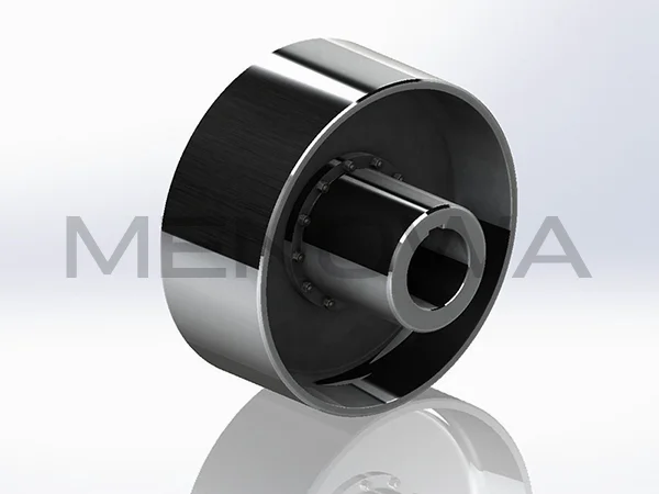
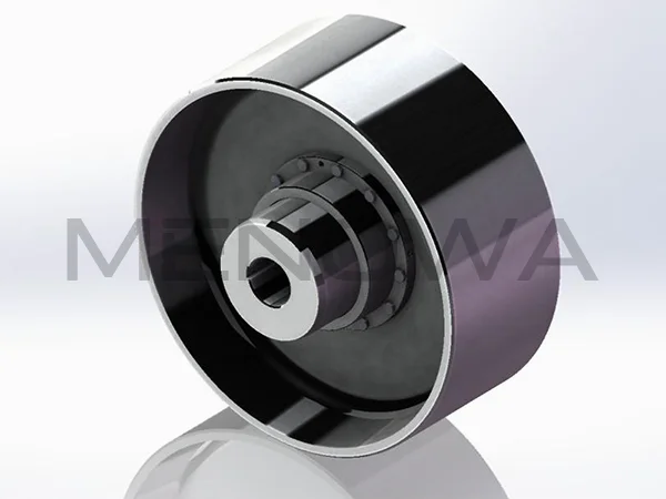
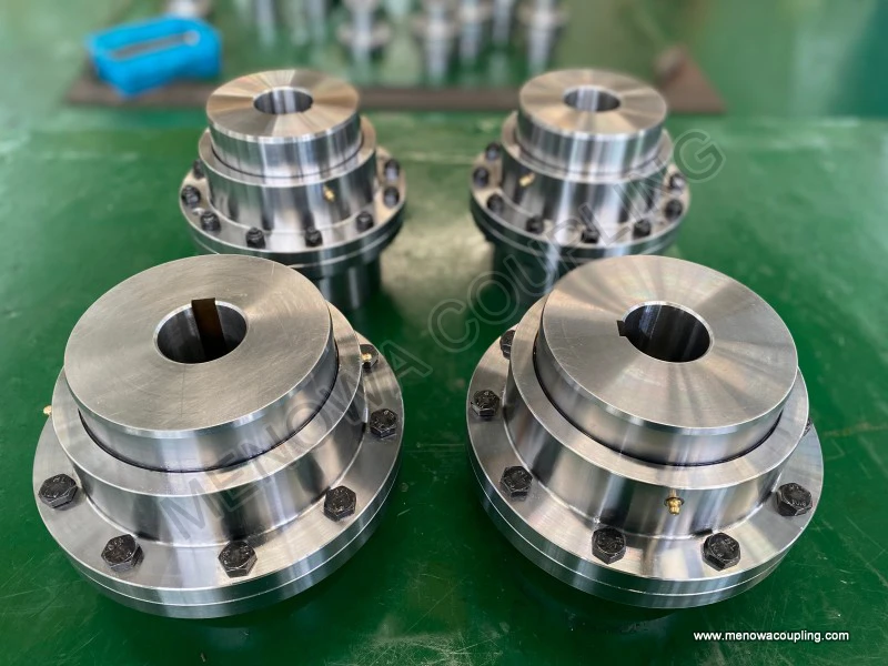
There are several types of gear type couplings, each designed to suit specific application requirements based on factors such as torque capacity, misalignment compensation needs, and installation space. The most common types include straight tooth gear couplings and crowned (or drum-shaped) tooth gear couplings. Straight tooth gear couplings feature straight external teeth on the hubs and straight internal teeth on the sleeve. They are relatively simple in design and cost-effective, making them suitable for applications with low to moderate torque and minimal misalignment. However, their ability to compensate for angular misalignment is limited, as the straight teeth can experience uneven wear if the shafts are not properly aligned. Crowned tooth gear couplings, on the other hand, have external teeth that are slightly curved in the axial direction, resembling a drum shape. This design allows for greater angular misalignment compensation, as the curved teeth maintain full contact with the internal teeth of the sleeve even when the shafts are at an angle. Crowned tooth couplings also distribute the load more evenly across the gear teeth, reducing wear and increasing torque capacity, making them ideal for heavy-duty applications with significant misalignment.
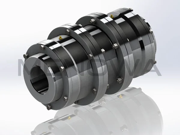
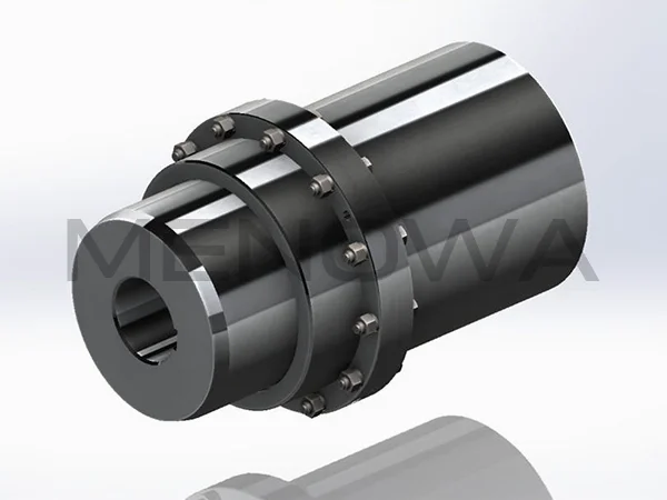
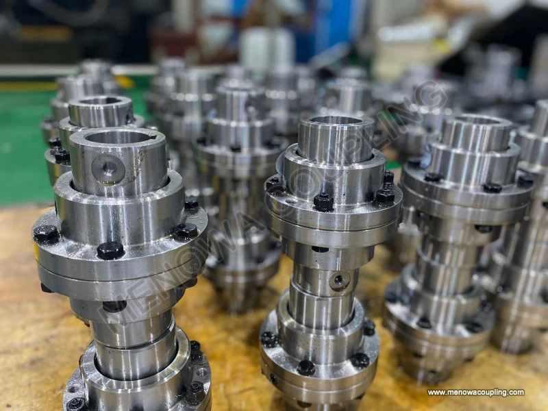
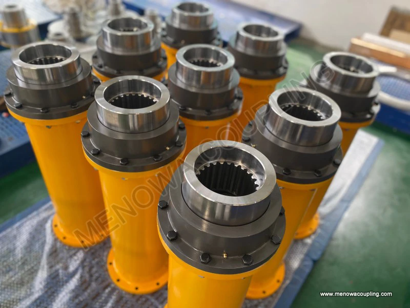
Another type of gear type coupling is the floating shaft gear coupling, which is used when the distance between the two shafts is too large to be connected by a standard coupling. This type of coupling consists of two gear couplings connected by an intermediate shaft (or floating shaft), which bridges the gap between the driving and driven shafts. The floating shaft gear coupling provides the same misalignment compensation as standard gear couplings while allowing for longer distances between shafts, making it suitable for applications such as conveyor systems, pumps, and large industrial machinery. Additionally, there are half gear couplings, which combine a gear hub on one side with a rigid hub on the other, designed for applications where only one side of the coupling requires flexibility.
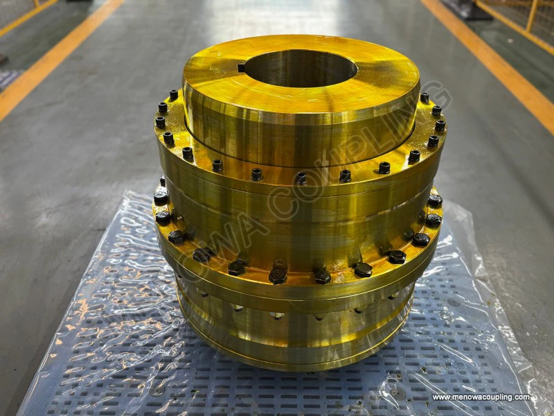
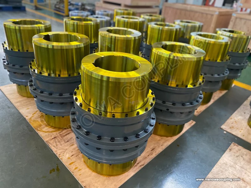
The design and manufacturing of gear type couplings require precise engineering to ensure optimal performance and durability. The gear teeth are typically machined using high-precision processes such as hobbing, shaping, or grinding to ensure a tight fit and smooth meshing. The choice of material is also critical, as the coupling must withstand high torque, friction, and potentially harsh operating conditions. Common materials used for gear type couplings include carbon steel, alloy steel, and stainless steel. Carbon steel is suitable for moderate torque applications, while alloy steel is used for heavy-duty applications due to its higher strength and wear resistance. Stainless steel is preferred in corrosive environments, such as marine or chemical processing applications, where resistance to rust and corrosion is essential. The gear teeth are often heat-treated to enhance their hardness and durability, reducing wear and extending the coupling’s service life.
Proper installation is essential to ensure the optimal performance and longevity of a gear type coupling. Before installation, it is important to inspect all components for damage, such as cracks, burrs, or worn gear teeth, and to clean the shafts and coupling parts to remove any dirt, grease, or debris. The gear hubs are typically mounted on the shafts using an interference fit, which may require heating the hubs in hot oil or an oven to expand them, allowing for easy installation on the shafts. Once the hubs are in place, they should be cooled to create a tight bond with the shafts. The inner gear sleeve is then positioned over the gear hubs, ensuring that the teeth mesh properly. It is crucial to check the alignment of the shafts using tools such as dial indicators to ensure that the misalignment is within the coupling’s allowable limits. Angular alignment can be checked by attaching a dial indicator to one hub and measuring the runout on the face of the other hub as it is rotated, while parallel alignment is checked by measuring the runout on the outer diameter of the other hub. Any misalignment beyond the allowable range can cause excessive wear on the gear teeth, reduce torque transfer efficiency, and lead to premature failure of the coupling.
Lubrication is another critical aspect of gear type coupling maintenance, as it reduces friction between the meshing gear teeth, prevents wear, and protects against corrosion. The type of lubricant used depends on the operating conditions, such as temperature, speed, and load. Common lubricants include grease and oil, with grease being preferred for most applications due to its ability to stay in place and provide long-lasting lubrication. The coupling should be filled with lubricant until it overflows from the lubrication holes, ensuring that all gear teeth are fully coated. It is important to regularly inspect the lubricant level and condition, as contaminated or degraded lubricant can cause significant damage to the gear teeth. The lubricant should be replaced at regular intervals, typically every 3000 hours of operation or once a year, whichever comes first. Additionally, the seals should be inspected regularly to ensure they are intact and functioning properly, as damaged seals can lead to lubricant leakage and contamination.
Regular inspection and maintenance are essential to identify potential issues early and prevent costly downtime. During inspections, the coupling should be checked for signs of wear, such as worn gear teeth, damaged seals, or loose fasteners. Worn gear teeth may appear smooth, chipped, or discolored, indicating that they need to be replaced. Loose bolts should be tightened to the recommended torque to ensure a secure connection. If any components are damaged or worn beyond repair, they should be replaced promptly to prevent further damage to the coupling or the connected machinery. It is also important to check the alignment of the shafts periodically, as misalignment can develop over time due to machine vibration, thermal expansion, or wear of other components.
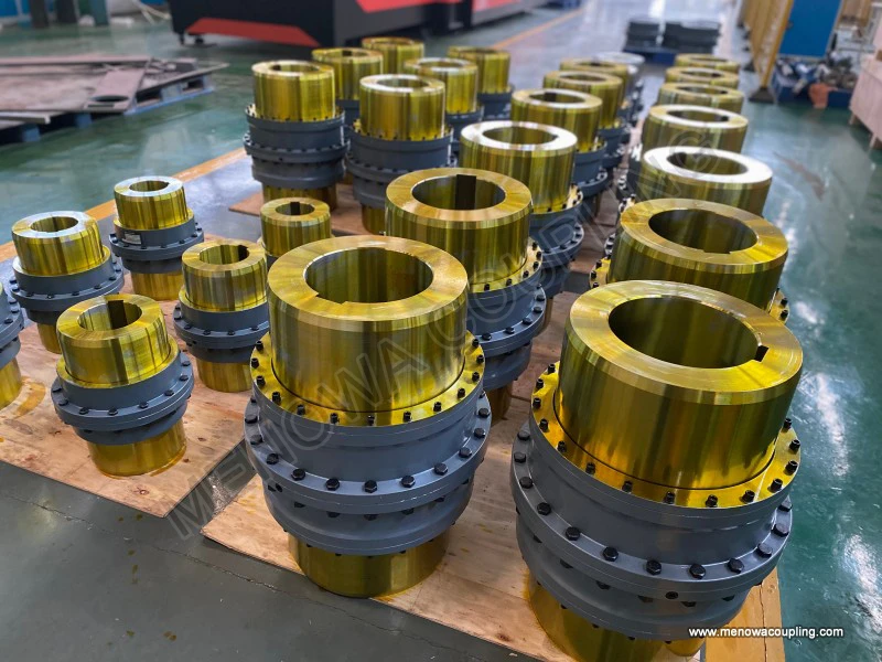
Gear type couplings are used in a wide range of industrial applications due to their high torque capacity, flexibility, and durability. In the metallurgical industry, they are used in rolling mills to connect the motor to the rolls, transmitting high torque while accommodating the slight misalignments that occur during operation. In the mining industry, they are used in conveyors, crushers, and pumps, where they must withstand harsh conditions and heavy loads. In power generation, gear type couplings are used in turbines and generators to connect the rotating components, ensuring efficient torque transfer. They are also used in manufacturing machinery, such as lathes, milling machines, and compressors, where precise torque transfer and misalignment compensation are essential. Additionally, gear type couplings are used in marine applications, such as ship propeller shafts, where they must withstand corrosive environments and high torque.
Despite their many advantages, gear type couplings have some limitations that should be considered when selecting a coupling for a specific application. One of the main limitations is the need for regular lubrication and maintenance, which can add to the operational costs. Additionally, gear type couplings are not suitable for applications with extremely high speeds, as the centrifugal force can cause the gear teeth to wear prematurely or even fail. They also generate more noise than some other coupling types, such as disc couplings, which may be a concern in noise-sensitive environments. However, these limitations are often outweighed by their high torque capacity and flexibility, making them the preferred choice for many heavy-duty applications.
In recent years, advancements in manufacturing technology have led to improvements in gear type coupling design and performance. The use of computer-aided design (CAD) and finite element analysis (FEA) has allowed engineers to optimize the gear tooth profile, resulting in better load distribution, increased torque capacity, and improved misalignment compensation. Additionally, the development of new materials and heat treatment processes has enhanced the durability and wear resistance of gear type couplings, extending their service life and reducing maintenance requirements. These advancements have made gear type couplings even more reliable and efficient, ensuring their continued use in a wide range of industrial applications.
In conclusion, a gear type coupling is a vital mechanical component that plays a critical role in industrial transmission systems. Its ability to transmit high torque while compensating for minor misalignments makes it indispensable in heavy-duty applications across various industries. By understanding its structural components, working principles, types, installation procedures, and maintenance requirements, engineers and maintenance personnel can ensure that gear type couplings operate efficiently and reliably, minimizing downtime and reducing operational costs. As manufacturing technology continues to advance, gear type couplings are likely to become even more efficient and durable, further solidifying their position as a key component in modern mechanical systems.
Post Date: Apr 29, 2026
https://www.menowacoupling.com/china-coupling/diagram-of-gear-type-coupling.html
Products
Tags
Supply
Related Articles
Size Chart of Gear Type Coupling
A size chart of gear type coupling is an indispensable reference tool in industrial power transmission systems, serving as a bridge between the functional requirements of machinery and the technical specifications of the coupling itself. It systematically organizes key dimensional and performance parameters, allowing en…Barrel Gear Coupling Hubs
Barrel gear coupling hubs stand as indispensable foundational mechanical components within modern power transmission systems, serving as the key connecting medium that links driving shafts and driven shafts to achieve stable torque transfer, rotational motion synchronization, and effective compensation for various shaft…Working Principle of Gear Type Coupling
A gear type coupling is a mechanical device specifically designed to connect two rotating shafts, enabling the efficient transmission of torque and rotational motion while accommodating a certain degree of misalignment between the shafts. Unlike rigid couplings that require precise alignment to function properly, gear t…Barrel Gear Coupling Sleeves
Barrel gear coupling sleeves stand as essential structural and functional components within modern mechanical power transmission systems, serving as the central connecting medium that bridges driving and driven shafts across a vast range of industrial machinery and rotating equipment. In every mechanical setup that reli…Gear Type Coupling For Sale
A gear type coupling is a versatile and robust mechanical device designed to connect two rotating shafts, enabling the efficient transmission of torque while accommodating a certain degree of misalignment between the shafts. This type of coupling is widely recognized for its ability to handle heavy loads and harsh opera…Gear Type Coupling Vendor In China
In the global mechanical transmission industry, gear type couplings play an indispensable role as key components that connect rotating shafts, transmit torque, and compensate for axial, radial, and angular displacements between shafts. As one of the world’s major manufacturing hubs, China has nurtured a large number of…Gear Type Coupling Production
Gear type couplings are essential mechanical components widely used in various industrial fields to connect two shafts and transmit torque while accommodating minor misalignments. The production of gear type couplings is a complex and precise process that requires strict control over every link, from material selection …
 WeChat
 WhatsApp