Working Principle of Gear Type Coupling
A gear type coupling is a mechanical device specifically designed to connect two rotating shafts, enabling the efficient transmission of torque and rotational motion while accommodating a certain degree of misalignment between the shafts. Unlike rigid couplings that require precise alignment to function properly, gear type couplings offer flexibility, making them indispensable in various industrial applications where perfect shaft alignment is difficult to achieve or maintain. The core functionality of a gear type coupling relies on the meshing of gear teeth, which not only ensures a secure connection between the two shafts but also allows for slight movements in different directions, thereby reducing stress on the connected machinery and extending the overall service life of the transmission system. To fully understand how a gear type coupling works, it is essential to examine its structural components, the mechanism of torque transmission, the types of misalignment it can compensate for, and the factors that influence its performance and durability.
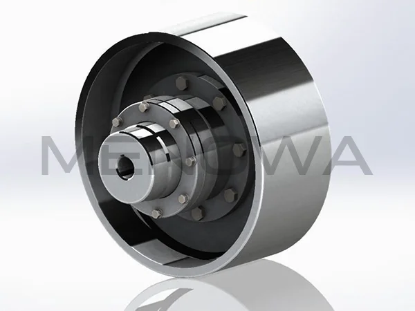
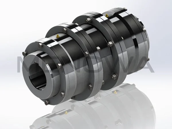
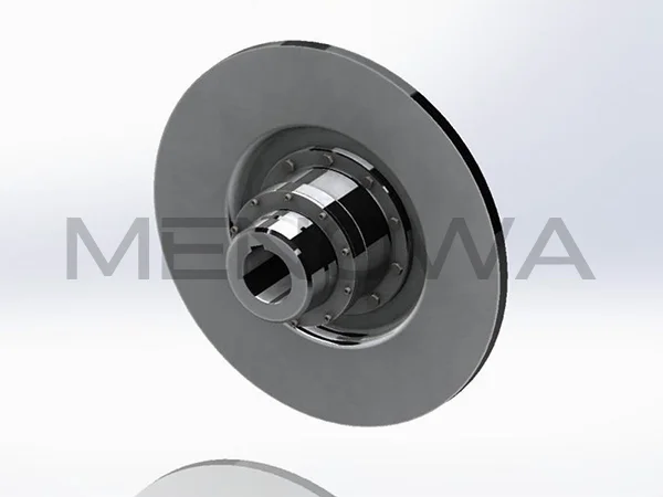
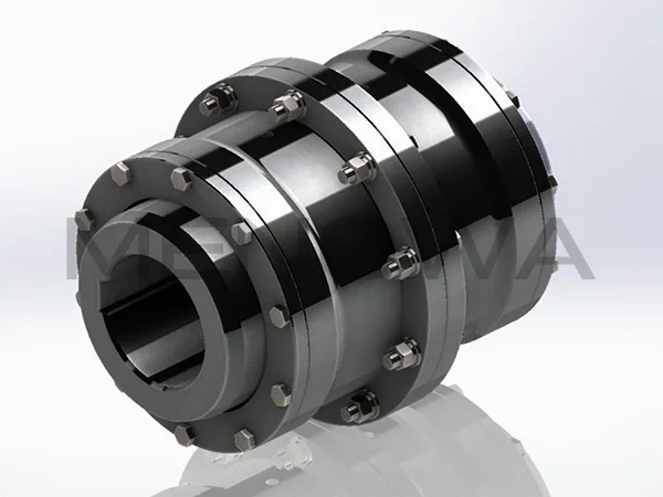
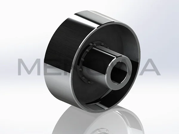
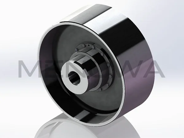
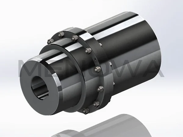
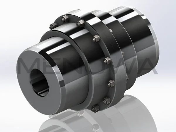
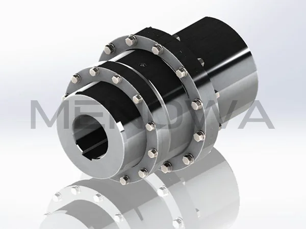
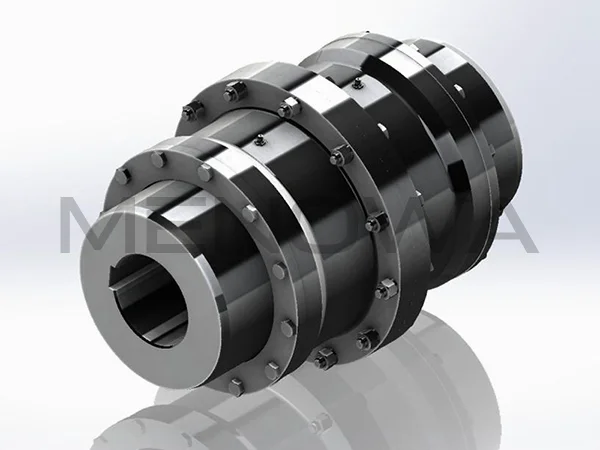
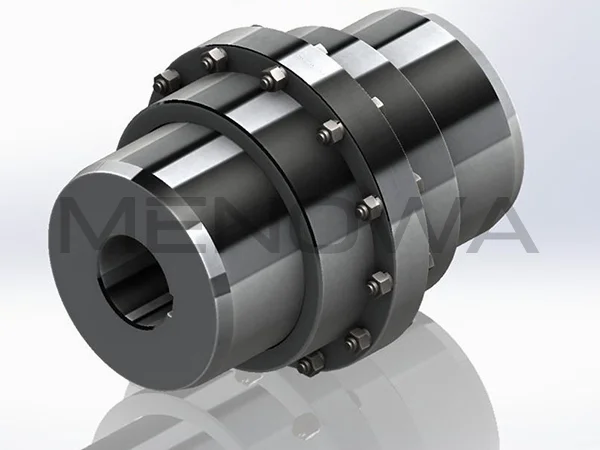
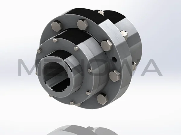
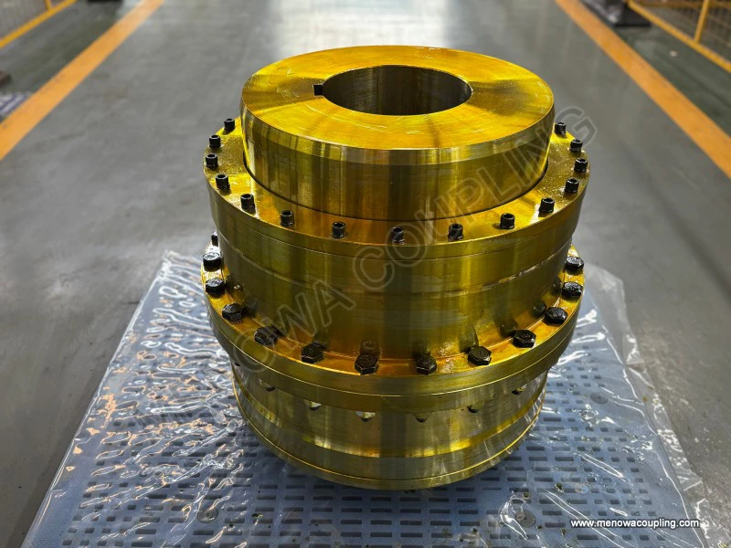
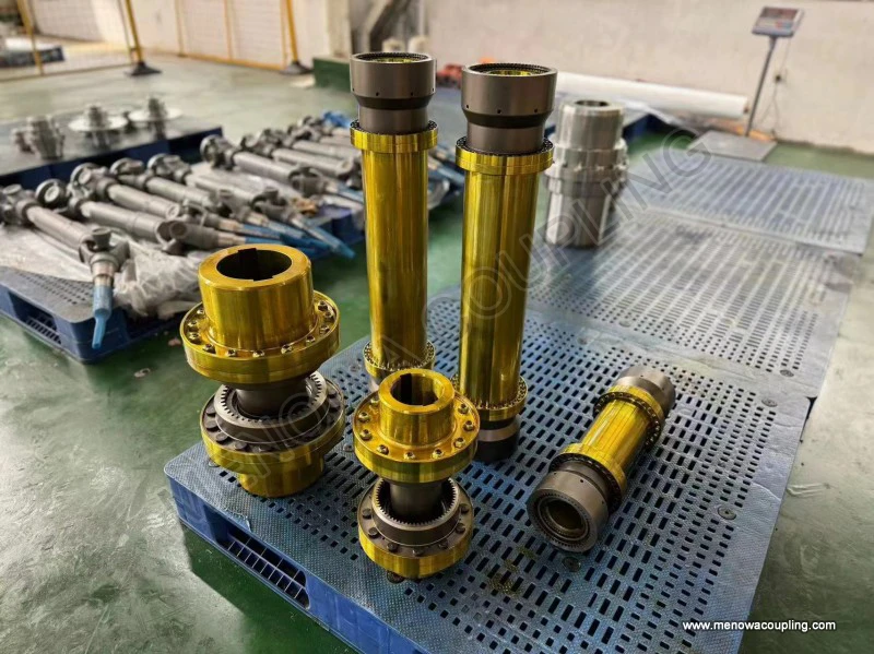
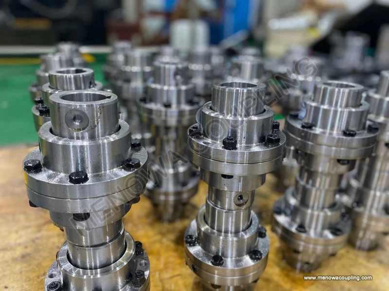
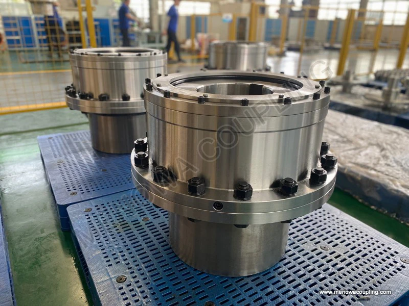
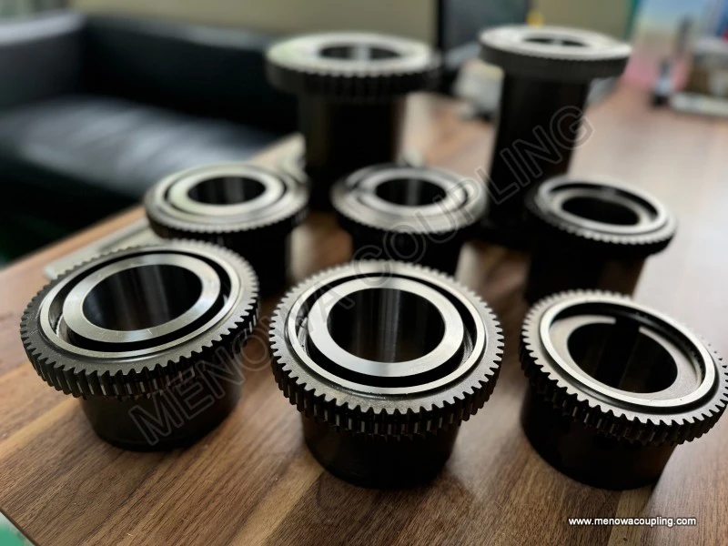
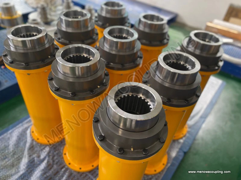
At its most basic level, a gear type coupling consists of several key components that work together seamlessly to facilitate torque transmission and misalignment compensation. The primary components include two outer gear hubs (also known as gear sleeves), each with external gear teeth, and one or two inner gear rings (or sleeves) with internal gear teeth that mesh with the external teeth of the hubs. In some designs, a intermediate shaft may be used to connect the two gear hubs, particularly in applications where the distance between the two shafts is significant. Each outer gear hub is securely attached to the end of one of the shafts that need to be connected, typically using keys, splines, or interference fits to ensure a tight and secure connection that can withstand high torque loads. The inner gear ring(s) then enclose the outer gear hubs, with the internal teeth of the ring meshing perfectly with the external teeth of the hubs. This meshing relationship is the foundation of the gear type coupling’s ability to transmit torque, as it creates a direct mechanical link between the two shafts.

The working principle of torque transmission in a gear type coupling is rooted in the basic mechanics of gear meshing. When one shaft rotates, it drives the outer gear hub attached to it, which in turn causes the external gear teeth to engage with the internal teeth of the inner gear ring. As the outer gear hub rotates, the meshing teeth transfer rotational force to the inner gear ring, which then transmits this force to the other outer gear hub (and thus the second shaft). This transfer of torque is efficient because the gear teeth are designed to distribute the load evenly across the contact surface, minimizing stress concentrations and ensuring that the maximum amount of rotational energy is transmitted from one shaft to the other. The gear teeth in a gear type coupling are typically cut using involute profiles, which are widely used in gear design due to their ability to maintain a constant velocity ratio during meshing, even when there is a slight misalignment between the gears. This constant velocity ratio is crucial for applications where precise speed control is required, as it prevents fluctuations in rotational speed that could damage the connected equipment or compromise the quality of the work being performed.
One of the most important features of a gear type coupling is its ability to compensate for misalignment between the two connected shafts. In industrial settings, perfect alignment between shafts is often difficult to achieve due to factors such as installation errors, thermal expansion and contraction of machinery during operation, foundation settlement, and vibrations. Misalignment can occur in three main forms: angular misalignment, radial misalignment, and axial misalignment. Angular misalignment happens when the axes of the two shafts are not parallel but intersect at a point, while radial misalignment occurs when the axes are parallel but offset from each other. Axial misalignment, on the other hand, is a linear displacement of one shaft relative to the other along the axis of rotation. Gear type couplings are designed to accommodate all three types of misalignment to varying degrees, depending on their specific design.
The ability to compensate for misalignment is primarily achieved through the design of the gear teeth and the overall structure of the coupling. In the case of angular misalignment, the gear teeth are often crowned (curved) along their length, which allows the external teeth of the hub to mesh with the internal teeth of the ring even when the shafts are at an angle. This crowned design ensures that the contact between the teeth remains uniform, even as the angle between the shafts changes, preventing excessive wear on the tooth surfaces. For radial misalignment, the clearance between the gear teeth and the flexibility of the coupling structure allow the outer gear hubs to move slightly relative to the inner gear ring, accommodating the offset between the shafts. Axial misalignment is compensated for by the ability of the outer gear hubs to slide axially within the inner gear ring, as the gear teeth are designed to allow this movement without losing meshing contact. This axial flexibility is particularly important in applications where thermal expansion causes the shafts to lengthen or shorten during operation, as it prevents the build-up of axial stress that could damage the coupling or the connected machinery.
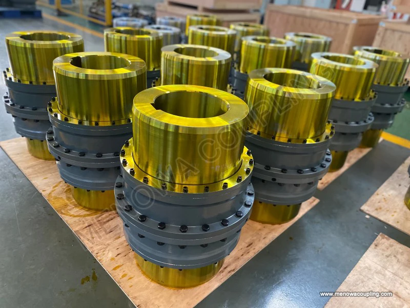
There are two main types of gear type couplings: straight-tooth gear couplings and crowned-tooth (or drum-shaped) gear couplings. Straight-tooth gear couplings have teeth that are cut parallel to the axis of rotation, and while they are capable of transmitting high torque, they have limited misalignment compensation capabilities, particularly for angular misalignment. This is because the straight teeth can only maintain proper meshing when the shafts are nearly perfectly aligned; any significant angular misalignment will cause uneven contact between the teeth, leading to increased wear and reduced service life. Crowned-tooth gear couplings, on the other hand, have teeth that are curved along their length, with the crown radius centered on the axis of the shaft. This design allows for much greater angular misalignment compensation, as the curved teeth can mesh smoothly even when the shafts are at an angle of up to 4 or 5 degrees, depending on the specific design. Crowned-tooth gear couplings are also more resistant to wear and fatigue, making them the preferred choice for most industrial applications where misalignment is a common issue.
Another critical aspect of the working principle of gear type couplings is the role of lubrication. Since the gear teeth are in constant contact and relative motion during operation, friction between the teeth can lead to wear, heat generation, and eventual failure if not properly lubricated. Lubrication serves several key purposes: it reduces friction between the meshing teeth, minimizes wear and tear, dissipates heat generated by friction, and prevents corrosion of the gear surfaces. The type of lubricant used depends on the operating conditions of the coupling, including the torque load, rotational speed, and environmental factors such as temperature and humidity. Common lubricants used for gear type couplings include mineral oil-based lubricants, synthetic lubricants, and lithium soap-based greases with extreme pressure (EP) additives. These lubricants are designed to form a protective film between the gear teeth, ensuring smooth meshing and reducing the risk of metal-to-metal contact.
The lubrication process for gear type couplings typically involves filling the coupling housing with the appropriate lubricant, ensuring that all meshing surfaces are fully coated. In some cases, particularly for large or high-speed couplings, a forced lubrication system may be used, where lubricant is pumped into the coupling under pressure to ensure continuous and uniform lubrication. Regular lubrication maintenance is essential to ensure the longevity of the coupling; this includes periodic inspection of the lubricant level, checking for contamination (such as dirt, metal particles, or water), and replacing the lubricant at specified intervals. Failure to maintain proper lubrication can lead to premature wear of the gear teeth, increased friction and heat, and ultimately, coupling failure, which can result in costly downtime and equipment damage.
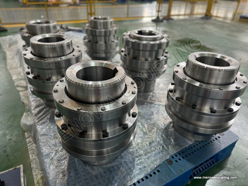
Sealing is another important component of gear type couplings, as it helps to retain the lubricant within the coupling and prevent the ingress of contaminants such as dirt, dust, and moisture. Contaminants can damage the gear teeth and reduce the effectiveness of the lubricant, leading to increased wear and corrosion. Common sealing mechanisms used in gear type couplings include lip seals, O-rings, and迷宫式密封 (labyrinth seals). Lip seals are designed to form a tight seal around the outer gear hub, preventing lubricant leakage and keeping contaminants out. O-rings are used to seal the joints between the coupling components, such as between the inner gear ring and the end caps. Labyrinth seals, which consist of a series of concentric grooves and ridges, are particularly effective in high-speed applications, as they create a tortuous path that prevents contaminants from entering the coupling while allowing for slight axial movement of the shafts.
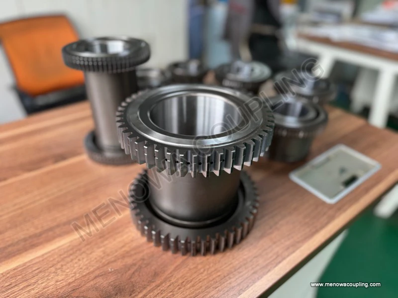
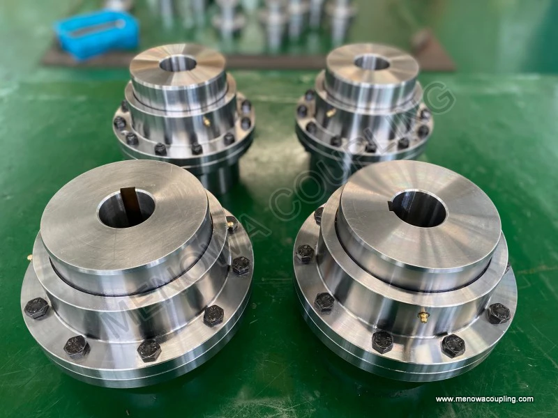
The performance of a gear type coupling is influenced by several factors, including the material used in its construction, the design of the gear teeth, the level of lubrication, and the operating conditions. The components of a gear type coupling are typically made from high-strength materials such as alloy steel, which offers excellent durability, strength, and resistance to wear and fatigue. The gear teeth are often heat-treated (such as through carburizing, quenching, or tempering) to enhance their hardness and wear resistance, ensuring that they can withstand the high torque loads and repeated meshing cycles encountered in industrial applications. The number and size of the gear teeth also play a role in the coupling’s performance; more teeth can distribute the load more evenly, while larger teeth can handle higher torque loads.
Operating conditions such as torque load, rotational speed, and temperature also have a significant impact on the performance and service life of a gear type coupling. Gear type couplings are designed to handle a wide range of torque loads, from small to very large, making them suitable for applications ranging from light-duty machinery to heavy-duty industrial equipment such as rolling mills, crushers, and turbines. However, operating the coupling beyond its rated torque capacity can lead to premature failure, as the gear teeth may become overloaded and sustain damage. Rotational speed is another important factor; high-speed operation can generate significant centrifugal forces, which can affect the stability of the coupling and increase the risk of lubricant leakage. In high-speed applications, the coupling must be carefully balanced to minimize vibrations and ensure smooth operation. Temperature also affects the performance of the coupling; extreme temperatures can cause the lubricant to break down, reducing its effectiveness, and can also cause thermal expansion or contraction of the coupling components, leading to changes in alignment and increased stress.
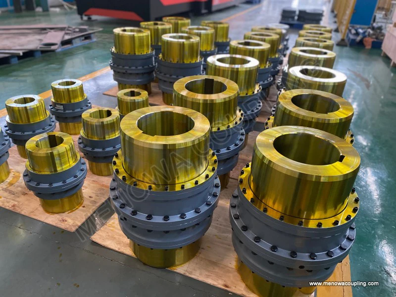
Gear type couplings are widely used in various industrial sectors due to their ability to transmit high torque, accommodate misalignment, and operate reliably in harsh conditions. Some common applications include metallurgy, where they are used in rolling mills and steel processing equipment; mining, where they connect the shafts of crushers, conveyors, and other heavy machinery; power generation, where they are used in turbines and generators; and marine applications, where they are used in propulsion systems. They are also used in manufacturing machinery, such as pumps, compressors, and extruders, where precise torque transmission and misalignment compensation are essential.
Despite their many advantages, gear type couplings do have some limitations. One of the main limitations is their requirement for regular maintenance, particularly lubrication and sealing checks. Without proper maintenance, the coupling’s performance can degrade rapidly, leading to premature failure. Another limitation is that they can generate more noise and vibration compared to some other types of couplings, such as flexible couplings, which can be a concern in applications where noise reduction is important. Additionally, gear type couplings are generally bulkier and heavier than other coupling types, which can be a disadvantage in applications where space is limited.
In conclusion, the working principle of a gear type coupling revolves around the meshing of external and internal gear teeth to transmit torque between two rotating shafts, while accommodating angular, radial, and axial misalignment. The key components of the coupling, including the outer gear hubs, inner gear rings, and sealing and lubrication systems, work together to ensure efficient and reliable operation. The design of the gear teeth, particularly the use of crowned teeth, allows for greater misalignment compensation, while proper lubrication and sealing prevent wear and contamination, extending the coupling’s service life. Gear type couplings are essential components in many industrial applications, providing a robust and flexible solution for torque transmission in environments where perfect shaft alignment is difficult to maintain. Understanding their working principle is crucial for selecting the right coupling for a specific application, ensuring proper installation and maintenance, and maximizing the performance and longevity of the transmission system.
Post Date: Apr 27, 2026
https://www.menowacoupling.com/china-coupling/working-principle-of-gear-type-coupling.html
Products
Tags
Supply
Related Articles
Diagram of Gear Type Coupling
A gear type coupling is a crucial mechanical component widely utilized in industrial transmission systems to connect two rotating shafts, enabling the efficient transfer of torque while accommodating minor misalignments that may occur during operation. Unlike rigid couplings that require precise alignment between shafts…Gear Type Coupling For Sale
A gear type coupling is a versatile and robust mechanical device designed to connect two rotating shafts, enabling the efficient transmission of torque while accommodating a certain degree of misalignment between the shafts. This type of coupling is widely recognized for its ability to handle heavy loads and harsh opera…Gear Type Coupling Vendor In China
In the global mechanical transmission industry, gear type couplings play an indispensable role as key components that connect rotating shafts, transmit torque, and compensate for axial, radial, and angular displacements between shafts. As one of the world’s major manufacturing hubs, China has nurtured a large number of…Gear Type Coupling Production
Gear type couplings are essential mechanical components widely used in various industrial fields to connect two shafts and transmit torque while accommodating minor misalignments. The production of gear type couplings is a complex and precise process that requires strict control over every link, from material selection …Size Chart of Gear Type Coupling
A size chart of gear type coupling is an indispensable reference tool in industrial power transmission systems, serving as a bridge between the functional requirements of machinery and the technical specifications of the coupling itself. It systematically organizes key dimensional and performance parameters, allowing en…Barrel Gear Coupling Hubs
Barrel gear coupling hubs stand as indispensable foundational mechanical components within modern power transmission systems, serving as the key connecting medium that links driving shafts and driven shafts to achieve stable torque transfer, rotational motion synchronization, and effective compensation for various shaft…Barrel Gear Coupling Sleeves
Barrel gear coupling sleeves stand as essential structural and functional components within modern mechanical power transmission systems, serving as the central connecting medium that bridges driving and driven shafts across a vast range of industrial machinery and rotating equipment. In every mechanical setup that reli…
 WeChat
 WhatsApp