Size Chart of Gear Type Coupling
A size chart of gear type coupling is an indispensable reference tool in industrial power transmission systems, serving as a bridge between the functional requirements of machinery and the technical specifications of the coupling itself. It systematically organizes key dimensional and performance parameters, allowing engineers, technicians, and procurement professionals to select the most suitable gear coupling for a specific application with precision and efficiency. Unlike generic mechanical component charts, the size chart for gear type couplings is tailored to the unique structural characteristics of these devices—their ability to transmit high torque, accommodate shaft misalignment, and operate under harsh industrial conditions—making every parameter on the chart critical to the overall performance and longevity of the machinery it serves. Understanding how to interpret and apply this chart is not only essential for proper coupling selection but also for ensuring the safety, reliability, and cost-effectiveness of the entire power transmission system.
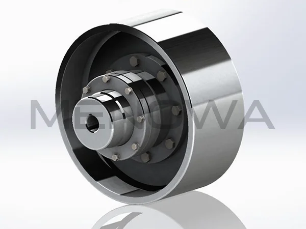
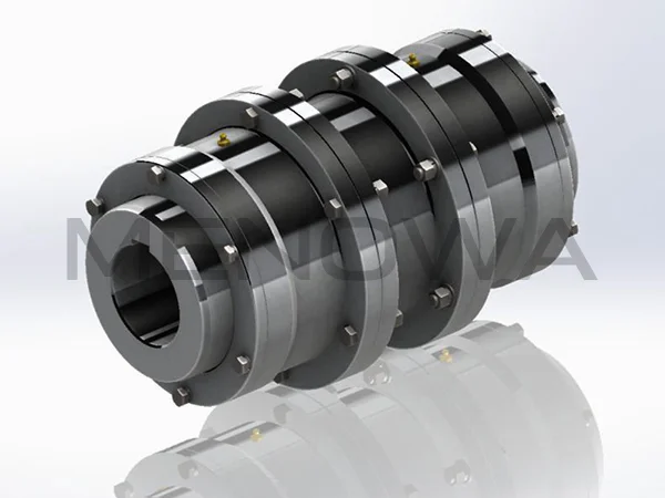
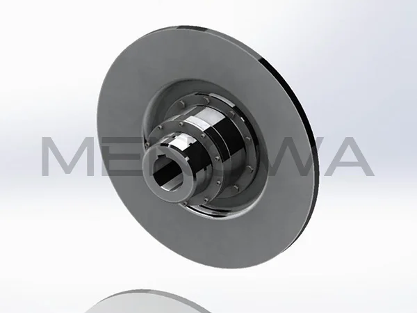
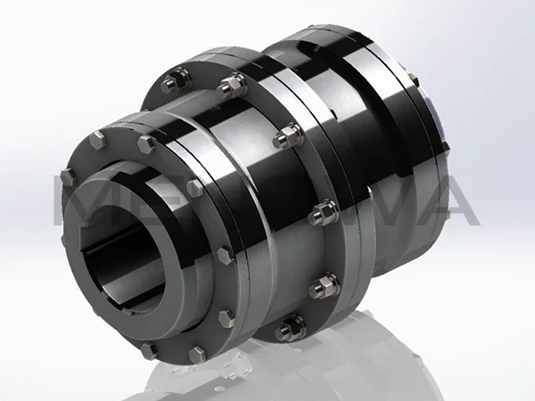
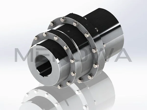
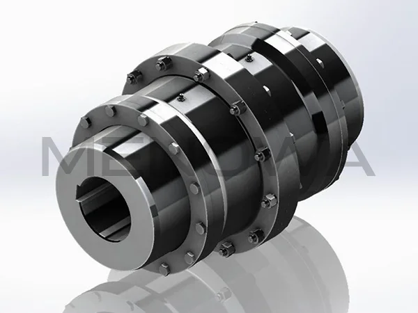
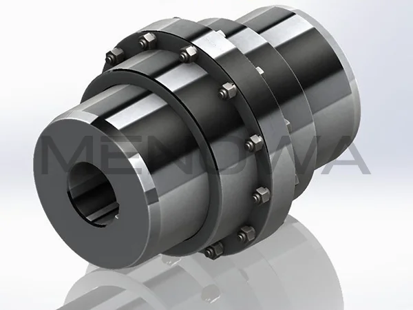
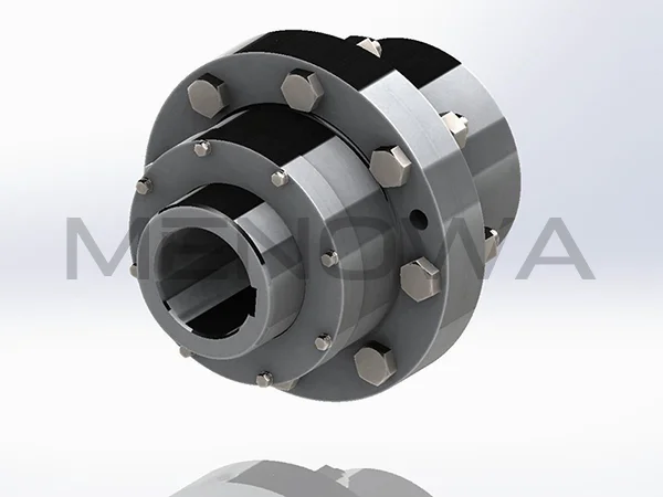
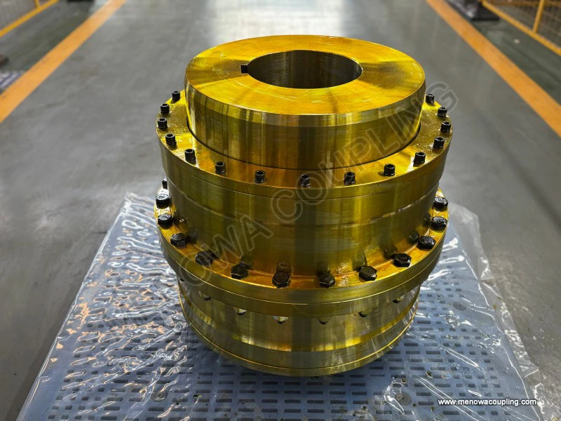
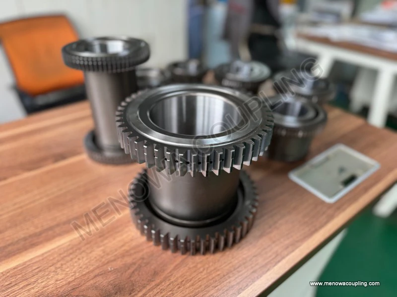
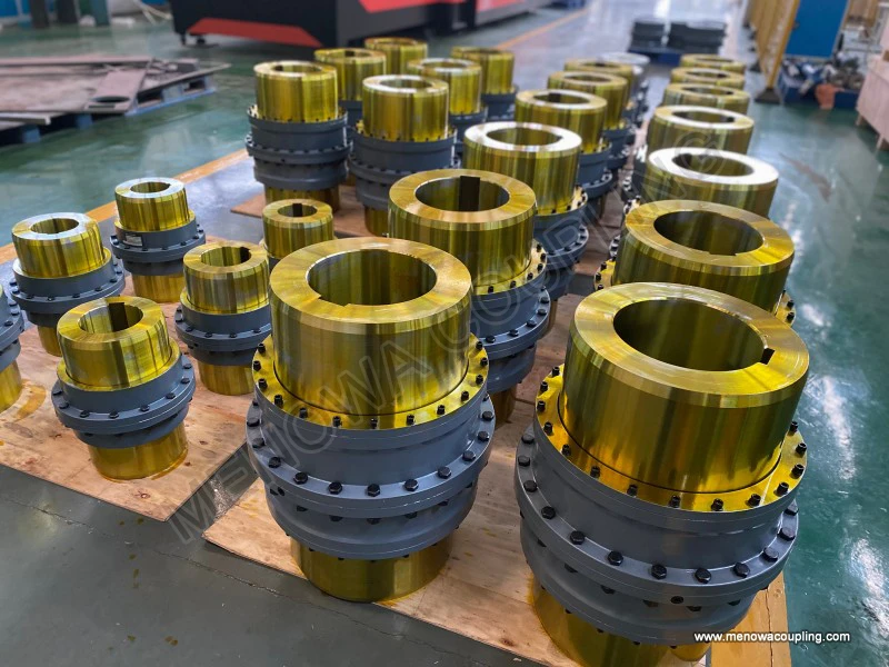
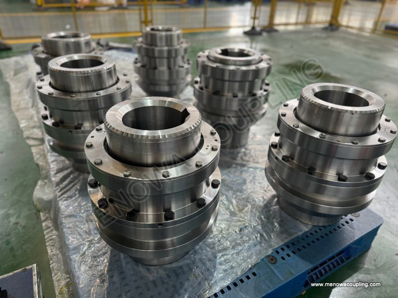
Gear type couplings are widely used in various industrial sectors, including manufacturing, mining, power generation, automotive, and aerospace, due to their robust design and versatile performance. These couplings consist of two gear hubs with external teeth that mesh with internal teeth on a sleeve or flange, creating a secure connection between two rotating shafts. The size chart encapsulates all the critical dimensions and performance metrics that define the capabilities of each coupling model, enabling users to match the coupling’s specifications to the specific demands of their application. Whether it is a low-speed, heavy-load application in a mining conveyor or a high-speed, precision application in a power generation turbine, the size chart provides the necessary data to make an informed decision, avoiding the risks of over-sizing or under-sizing which can lead to premature failure, increased maintenance costs, or even catastrophic equipment damage.

At the core of any gear type coupling size chart are the dimensional parameters, which directly influence the coupling’s compatibility with the shafts it connects and its ability to fit within the available installation space. These dimensional parameters typically include the bore diameter, hub length, sleeve length, overall coupling length, flange diameter (for flanged models), and the number and size of fasteners such as bolts or studs. The bore diameter is one of the most fundamental parameters, as it must match the diameter of the shafts being connected to ensure a secure fit. Size charts often list multiple bore diameter options for each coupling model, allowing for flexibility in adapting to different shaft sizes common in industrial machinery. For example, a single coupling model may be available with bore diameters ranging from a few millimeters to over 100 millimeters, catering to both small-scale equipment and large industrial machinery.
The hub length, which refers to the length of the gear hub that attaches to the shaft, is another critical dimensional parameter. A longer hub provides a larger contact area between the coupling and the shaft, distributing the torque more evenly and reducing the stress on the shaft and coupling interface. This is particularly important in high-torque applications where concentrated stress can lead to shaft wear or coupling slippage. The sleeve length, on the other hand, determines the amount of overlap between the gear hubs and the sleeve, which affects the coupling’s ability to accommodate misalignment. A longer sleeve typically allows for greater angular and parallel misalignment, making the coupling more versatile in applications where shaft alignment is challenging, such as in heavy machinery with dynamic loads or thermal expansion.
Overall coupling length is a key consideration for applications with limited installation space, such as in compact machinery or tight engine compartments. Size charts clearly indicate the overall length of each coupling model, enabling users to ensure that the coupling will fit within the available space without interfering with other components. Flange diameter, for flanged gear couplings, is important for determining the mounting footprint and the number of fasteners required to secure the coupling to the machinery. The size chart also specifies the size and quantity of fasteners, ensuring that the correct hardware is used during installation to maintain the coupling’s integrity and performance.
In addition to dimensional parameters, the size chart for gear type couplings includes critical performance parameters that define the coupling’s operational capabilities. The most important of these is torque capacity, which refers to the maximum amount of torque the coupling can transmit without suffering damage or failure. Torque capacity is influenced by several factors, including the material of the coupling components, the design of the gear teeth, and the overall size of the coupling. Size charts list the torque capacity for each model, typically in Newton-meters (Nm) or pound-feet (lb-ft), allowing users to select a coupling that can handle the maximum torque generated by the machinery. It is essential to select a coupling with a torque capacity that exceeds the maximum operating torque of the application to provide a safety margin, as sudden torque spikes or overloads can occur in industrial operations.
Another key performance parameter is the maximum operating speed, which refers to the highest rotational speed at which the coupling can operate safely and efficiently. Operating a coupling above its maximum speed can lead to excessive vibration, heat generation, and premature wear, as the centrifugal forces acting on the coupling components increase with speed. Size charts specify the maximum operating speed for each model, usually in revolutions per minute (RPM), helping users match the coupling to the rotational speed of the shafts. This is particularly important in high-speed applications such as turbines, compressors, and electric motors, where even a small deviation from the recommended speed can have significant consequences.
Gear type couplings are designed to accommodate three types of shaft misalignment: angular, parallel, and axial. Angular misalignment occurs when the two shafts are not perfectly aligned, forming an angle between them; parallel misalignment occurs when the shafts are offset parallel to each other; and axial misalignment occurs when the shafts move along their axial direction. The size chart specifies the maximum allowable misalignment for each type, giving users an indication of the coupling’s flexibility. For example, a coupling may be capable of accommodating up to 1.5 degrees of angular misalignment, 5 millimeters of parallel misalignment, and 10 millimeters of axial movement. Understanding these parameters is crucial for applications where shaft alignment is difficult to maintain, such as in machinery subject to thermal expansion, vibration, or structural deflection.
Material composition is another important factor included in many gear type coupling size charts, as it directly impacts the coupling’s strength, durability, and resistance to wear and corrosion. Common materials used in gear couplings include carbon steel, alloy steel, stainless steel, and sometimes non-ferrous metals such as bronze or aluminum. Carbon steel is widely used for general-purpose applications due to its strength and affordability, while alloy steel is preferred for high-torque or high-speed applications where greater strength and durability are required. Stainless steel is used in applications where corrosion resistance is critical, such as in food processing, chemical, or marine environments. The size chart may specify the material of the gear hubs, sleeve, and other components, allowing users to select a coupling that is compatible with the environmental conditions of their application.
Lubrication requirements are also often included in gear type coupling size charts, as proper lubrication is essential for reducing friction between the gear teeth, minimizing wear, and extending the coupling’s service life. Gear couplings require regular lubrication with a suitable grease or oil, and the size chart may specify the type of lubricant recommended, the lubrication interval, and the quantity of lubricant required. For example, some couplings may require high-temperature grease for applications with elevated operating temperatures, while others may use standard industrial grease. Proper lubrication not only reduces wear but also helps to dissipate heat generated during operation, preventing overheating and premature failure.
Interpreting a gear type coupling size chart requires a clear understanding of the application’s requirements and how each parameter on the chart relates to those requirements. The first step in using the chart is to determine the key requirements of the application, including the shaft diameter, maximum torque, operating speed, misalignment tolerance, installation space, and environmental conditions. Once these requirements are identified, users can refer to the size chart to find coupling models that match or exceed these specifications.
For example, if an application requires a coupling to connect two shafts with a diameter of 50 millimeters, transmit a maximum torque of 2000 Nm, operate at a speed of 1500 RPM, and accommodate up to 1 degree of angular misalignment, the user can consult the size chart to find all coupling models with a bore diameter of 50 millimeters, a torque capacity of at least 2000 Nm, a maximum operating speed of at least 1500 RPM, and a maximum angular misalignment of at least 1 degree. From this list, the user can then select the model that best fits the available installation space and other application-specific requirements, such as material compatibility or lubrication needs.
It is important to note that size charts are not one-size-fits-all, and different manufacturers may present their charts with slight variations in parameters or formatting. However, the core parameters—bore diameter, torque capacity, operating speed, misalignment tolerance, and key dimensions—are consistent across most size charts, making it possible to compare different models and select the most suitable one. Additionally, some size charts may include additional information such as weight, moment of inertia, or backlash, which can be useful for applications where weight or precision is a critical factor.
The importance of using a size chart correctly cannot be overstated, as improper coupling selection can lead to a range of problems. Under-sizing a coupling, for example, can result in the coupling being unable to handle the application’s torque, leading to gear tooth wear, shaft damage, or even coupling failure. This can cause unplanned downtime, costly repairs, and potential safety hazards. Over-sizing a coupling, on the other hand, can lead to unnecessary costs, as larger couplings are typically more expensive and may require more installation space. Additionally, an over-sized coupling may not fit within the available space or may add unnecessary weight to the machinery, affecting its overall performance.
In addition to selecting the correct coupling based on the size chart, proper installation and maintenance are also essential for ensuring the coupling’s performance and longevity. The size chart may provide guidance on installation procedures, such as the recommended torque for fasteners, the proper alignment method, and the lubrication requirements. Following these guidelines is crucial for ensuring that the coupling is installed correctly and operates as intended. Regular maintenance, including lubrication, inspection for wear or damage, and alignment checks, can help to identify potential issues early and prevent premature failure.
Gear type coupling size charts also play a valuable role in inventory management and procurement. By providing a comprehensive list of coupling models and their specifications, the chart allows procurement professionals to accurately identify the required coupling for each application, ensuring that the correct parts are ordered and in stock. This helps to reduce lead times, minimize inventory costs, and prevent delays in maintenance or equipment installation.
As industrial machinery becomes more advanced and demanding, the role of gear type coupling size charts continues to grow. Modern machinery often operates at higher speeds, transmits greater torque, and requires greater flexibility in handling misalignment, making accurate coupling selection more critical than ever. Size charts are constantly updated to reflect advances in coupling design and materials, ensuring that users have access to the most up-to-date information to make informed decisions.
In conclusion, a size chart of gear type coupling is a vital tool for anyone involved in the selection, installation, or maintenance of industrial power transmission systems. It provides a systematic and comprehensive overview of the key dimensional and performance parameters of gear couplings, enabling users to select the most suitable coupling for their specific application. By understanding how to interpret and apply the information in the size chart, engineers and technicians can ensure the safety, reliability, and efficiency of their machinery, reducing downtime, maintenance costs, and the risk of equipment failure. Whether for a small-scale application or a large industrial system, the size chart is an essential resource that underpins the successful operation of gear type couplings in a wide range of industrial settings.
Post Date: Apr 27, 2026
https://www.menowacoupling.com/china-coupling/size-chart-of-gear-type-coupling.html
Products
Tags
Supply
Related Articles
Working Principle of Gear Type Coupling
A gear type coupling is a mechanical device specifically designed to connect two rotating shafts, enabling the efficient transmission of torque and rotational motion while accommodating a certain degree of misalignment between the shafts. Unlike rigid couplings that require precise alignment to function properly, gear t…Barrel Gear Coupling Sleeves
Barrel gear coupling sleeves stand as essential structural and functional components within modern mechanical power transmission systems, serving as the central connecting medium that bridges driving and driven shafts across a vast range of industrial machinery and rotating equipment. In every mechanical setup that reli…Diagram of Gear Type Coupling
A gear type coupling is a crucial mechanical component widely utilized in industrial transmission systems to connect two rotating shafts, enabling the efficient transfer of torque while accommodating minor misalignments that may occur during operation. Unlike rigid couplings that require precise alignment between shafts…Gear Type Coupling For Sale
A gear type coupling is a versatile and robust mechanical device designed to connect two rotating shafts, enabling the efficient transmission of torque while accommodating a certain degree of misalignment between the shafts. This type of coupling is widely recognized for its ability to handle heavy loads and harsh opera…Gear Type Coupling Vendor In China
In the global mechanical transmission industry, gear type couplings play an indispensable role as key components that connect rotating shafts, transmit torque, and compensate for axial, radial, and angular displacements between shafts. As one of the world’s major manufacturing hubs, China has nurtured a large number of…Gear Type Coupling Production
Gear type couplings are essential mechanical components widely used in various industrial fields to connect two shafts and transmit torque while accommodating minor misalignments. The production of gear type couplings is a complex and precise process that requires strict control over every link, from material selection …Barrel Gear Coupling Hubs
Barrel gear coupling hubs stand as indispensable foundational mechanical components within modern power transmission systems, serving as the key connecting medium that links driving shafts and driven shafts to achieve stable torque transfer, rotational motion synchronization, and effective compensation for various shaft…
 WeChat
 WhatsApp