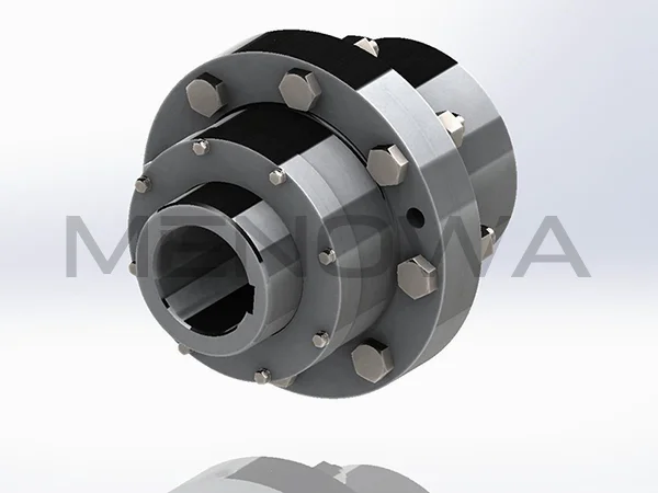
Diagram of Curved Tooth Coupling
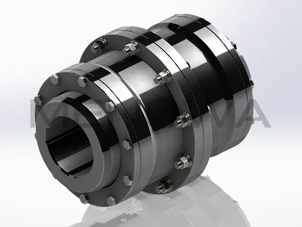
The diagram of curved tooth coupling intuitively presents the structural layout, meshing logic and spatial assembly relationship of this mainstream flexible transmission component, serving as a core technical reference for design optimization, model selection, installation and maintenance in the global industrial machinery market. As a high-performance gear coupling widely applied in international heavy-duty transmission systems, its structural diagram fully reflects the innovative curved tooth profile design and modular assembly characteristics that distinguish it from traditional straight-tooth gear couplings. Every structural unit displayed in the diagram corresponds to independent mechanical functions, and the overall matching relationship of each component determines the coupling’s core performance of high torque transmission, multi-directional misalignment compensation and low friction operation. In global industrial engineering, understanding the structural composition and working logic reflected in the curved tooth coupling diagram is the basic premise for standardized model selection, scene matching and long-term stable operation of equipment, and it also provides effective technical support for the iterative upgrading of transmission systems in various industrial fields.
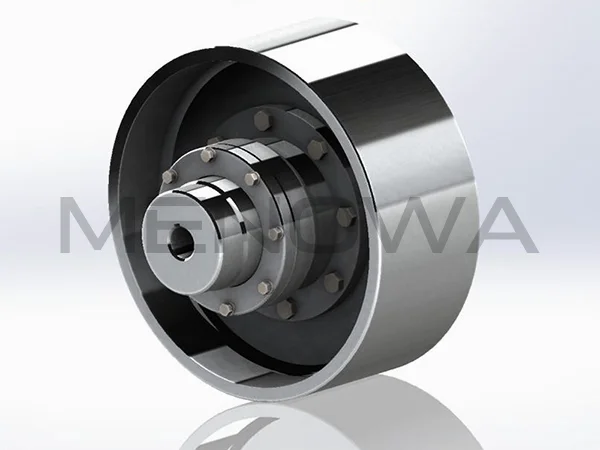
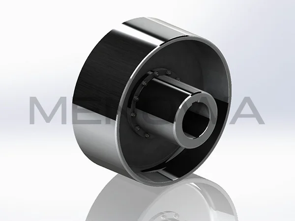
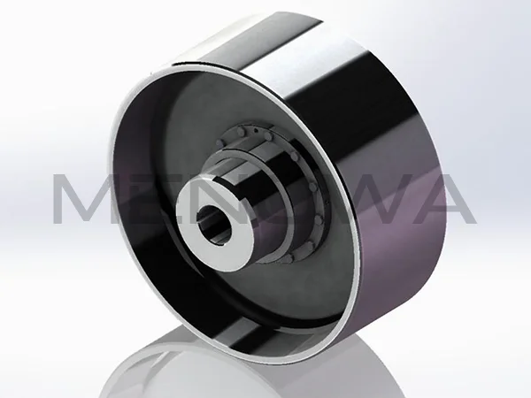
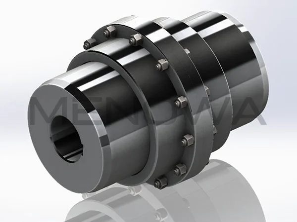
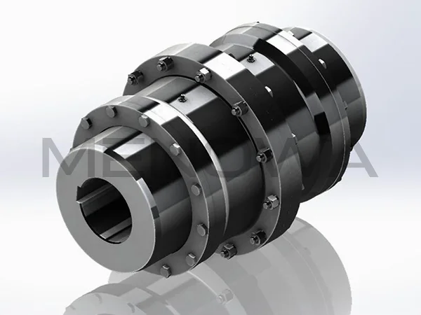
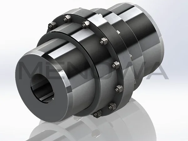
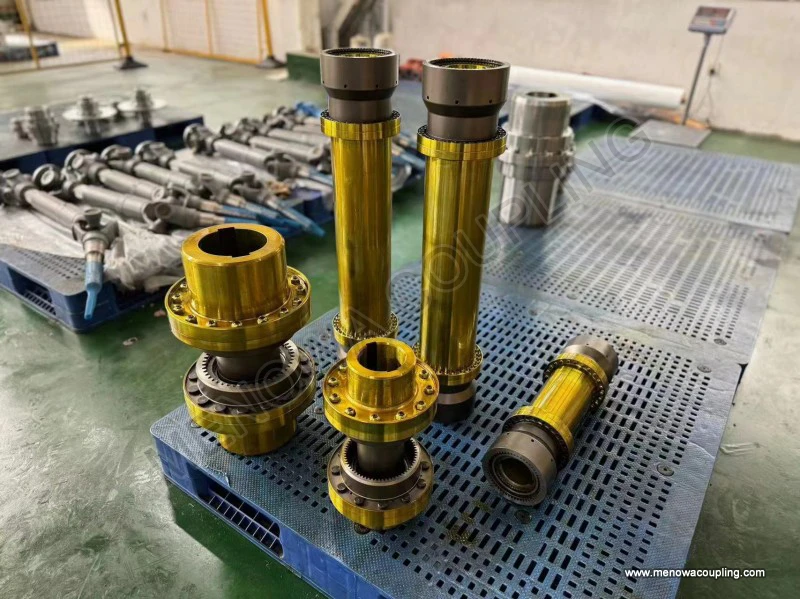
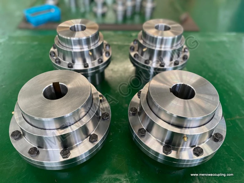
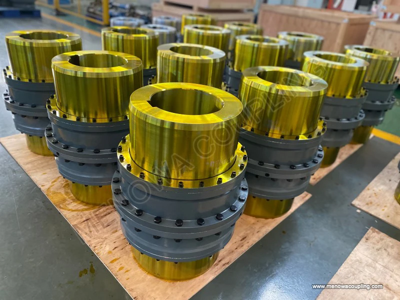
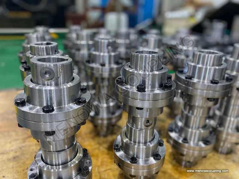
A complete curved tooth coupling diagram mainly displays two core matching parts, auxiliary sealing structures and fastening assemblies, with the meshing relationship between external curved tooth hubs and internal tooth sleeves being the most critical part of the entire diagram. Different from straight-tooth coupling diagrams that show linear tooth arrangement, the tooth profile part in the curved tooth coupling diagram presents a uniform spherical arc structure, with the spherical center of each curved tooth located on the central axis of the coupling shaft. This special geometric feature shown in the diagram is the fundamental reason why the product can adapt to angular, radial and axial misalignment simultaneously. The diagram clearly marks the reasonable tooth side gap reserved between meshing teeth, which is significantly optimized compared with conventional gear couplings. This gap design avoids rigid extrusion and friction between tooth surfaces during shaft displacement, and enables the coupling to generate flexible adaptive displacement during high-speed operation, effectively relieving mechanical stress concentration caused by installation errors, equipment thermal deformation and foundation vibration in industrial operation.
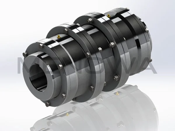
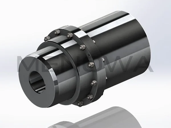
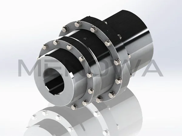
From the spatial layout shown in the diagram, the curved tooth coupling adopts a symmetrical modular structure. The external tooth hubs on both sides are connected with the driving and driven shafts respectively through keyway structures, and the middle internal tooth sleeve wraps the external curved teeth to form a closed meshing transmission unit. The diagram accurately shows the dimensional matching relationship between the hub inner hole, keyway and shaft diameter, as well as the assembly gap between the outer sleeve and the hub, which guides global engineering technicians to complete standardized installation and precision debugging. In addition, the diagram also presents the distribution position of sealing rings, grease injection holes and fastening bolts. The sealing components are symmetrically arranged at both ends of the meshing area to form a fully enclosed lubrication cavity, while the uniformly distributed fastening structures ensure the overall structural rigidity of the coupling under high torque load. The intuitive structural information conveyed by the diagram makes it a universal technical standard for coupling matching in cross-border industrial projects, equipment supporting and mechanical transformation projects worldwide.
Based on the structural characteristics reflected by the curved tooth coupling diagram, the global industrial industry has formed a set of standardized and universal selection methods and quantitative calculation formulas to ensure that the selected coupling can perfectly adapt to different working conditions and transmission requirements. The core selection calculation formula applicable to all industrial scenarios is the corrected working torque formula: Tc = K × Tn, where Tc represents the calculated working torque required for coupling selection, Tn stands for the rated steady-state torque of the mechanical transmission system, and K is the working condition correction safety factor. The value of the safety factor needs to be reasonably defined according to the actual operating state of global industrial equipment. For continuously operating equipment with stable load, uniform operation and no frequent start-stop, such as conventional industrial water pump sets and ventilation fan systems, the factor value can be controlled between 1.2 and 1.5. For general processing equipment with intermittent operation and minor load fluctuations, the factor ranges from 1.5 to 2.0. For heavy industrial equipment with frequent start-stop, obvious impact load and severe load fluctuation, including mining crushing equipment, marine power propulsion devices and metallurgical rolling machinery, the factor needs to be adjusted to 2.0 to 3.0 to cope with instantaneous peak torque and cyclic mechanical impact.
On the basis of torque calculation, multiple key parameters derived from the structural diagram need to be comprehensively verified to complete scientific selection. First is the maximum allowable speed, which is determined by the outer diameter, tooth structure and material characteristics shown in the diagram. Excessively high operating speed will produce excessive centrifugal force, leading to structural vibration, tooth surface fatigue and lubrication failure, so the actual operating speed of the equipment must be lower than the limit speed of the coupling. Second is the misalignment compensation range, which is directly reflected by the curved tooth radian and reserved gap in the diagram. The unique arc tooth profile allows the coupling to bear larger angular deviation than traditional couplings, which can effectively compensate for shaft position changes caused by equipment thermal expansion and contraction, installation deviation and long-term foundation settlement. Meanwhile, the axial displacement tolerance range marked in the diagram is a key indicator for the selection of high-temperature operating equipment, solving the transmission failure problem caused by thermal deformation of metal parts.
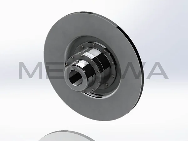
Spatial installation size matching is also a key selection criterion guided by the coupling diagram. The overall outer diameter, axial assembly length and hub inner hole parameters displayed in the diagram need to be matched with the equipment installation space and shaft diameter specifications. For compact automated production lines and precision processing equipment popular in European and American high-end manufacturing markets, small-size, low-inertia curved tooth couplings with compact structural dimensions are preferred to meet the requirements of high-speed precise transmission and limited installation space. For heavy-load equipment in mining, energy and marine engineering markets, large-specification couplings with high structural rigidity and large tooth surface contact area are selected to ensure stable transmission of ultra-high torque. In addition, the sealing structure form shown in the diagram should be selected in combination with the operating environment; enhanced sealing structural configurations are required for humid, dusty and corrosive working environments to avoid lubricant leakage and impurity invasion.
The structural advantages displayed in the curved tooth coupling diagram determine its wide adaptability in global industrial scenarios, covering heavy-load low-speed operation, high-speed precision transmission and harsh environment industrial production fields. In the global electric power industry, this type of coupling is widely used in the shaft connection of generator sets, steam turbines and wind power equipment. The symmetrical meshing structure shown in the diagram ensures uniform force on each tooth surface, stable torque transmission and low vibration noise, which can adapt to the long-term continuous unattended operation state of power equipment and effectively reduce the failure rate of transmission systems. The good misalignment compensation performance also solves the transmission instability problem caused by thermal deformation of power equipment during long-time operation, improving the overall operational efficiency of power stations.
In the international marine and offshore engineering market, curved tooth couplings have become indispensable core transmission components for ship power systems and offshore platform mechanical equipment. The complex marine working environment is accompanied by hull shaking, water flow impact and alternating temperature changes, which are easy to cause multi-directional misalignment of transmission shafts. The flexible adjustment space reserved by the curved tooth structure in the diagram can effectively absorb angular, radial and axial deviations, ensuring continuous and stable power transmission of ship main engines and propeller shafts. At the same time, the fully enclosed sealing structure shown in the diagram can resist the erosion of humid air and salt spray in marine environments, avoid internal tooth surface corrosion and lubrication failure, and greatly extend the service life of transmission components in marine equipment.
The global mining, metallurgy and building materials industries are important application markets for curved tooth couplings, where equipment often operates with heavy load, strong impact and high vibration. The large-area arc tooth meshing form displayed in the diagram disperses unit tooth surface pressure, avoids local stress concentration and tooth surface wear failure under impact load, and has far higher load-bearing capacity and fatigue resistance than straight-tooth couplings. Mining conveyors, crushers and metallurgical rolling equipment have severe load fluctuations during operation, and the flexible buffering performance of curved tooth structures can effectively absorb mechanical vibration and impact force, protect equipment bearings and transmission shafts from damage, and reduce the maintenance cost of heavy industrial equipment. In global large-scale mineral processing and metallurgical production projects, this coupling has become the preferred transmission component due to its high stability and strong impact resistance.
In the petrochemical and new energy industries, industrial equipment such as oil and gas drilling rigs, chemical delivery pumps and new energy power generation equipment usually operates in variable temperature, dusty and corrosive harsh environments. The structural characteristics reflected in the curved tooth coupling diagram, including reliable sealing performance, stable high and low temperature resistance and low wear characteristics, enable it to maintain efficient and stable transmission state in extreme working conditions. The closed lubrication cavity structure can lock lubricating media for long-term operation, reduce the friction coefficient of tooth surfaces, and avoid transmission efficiency attenuation caused by dry friction. The stable structural rigidity also ensures that the coupling will not produce structural deformation or transmission clearance under variable load conditions, meeting the long-term and high-reliability operation requirements of energy chemical equipment.
In high-precision manufacturing fields such as CNC machine tools and automated production equipment in the global high-end manufacturing market, the application advantages of curved tooth couplings are reflected in zero-clearance precise transmission and high dynamic response. The precise tooth profile matching design shown in the diagram eliminates transmission clearance, realizes synchronous rotation of driving and driven shafts, and meets the high-precision positioning and processing requirements of precision mechanical equipment. The low moment of inertia structural feature also enables the coupling to adapt to frequent high-speed start-stop and speed regulation operations of automated equipment, improve production and processing efficiency, and ensure the consistency of product processing accuracy.
With the continuous development of global industrial manufacturing towards high precision, high load and high efficiency, the structural design of curved tooth couplings is also constantly optimized and upgraded on the basis of traditional structural diagrams. Modern optimized structural diagrams pay more attention to lightweight integration, low noise operation and full-cycle durability, and further improve material utilization and transmission efficiency while ensuring load-bearing performance. In the global industrial supporting market, technicians always take the coupling structural diagram as the basic technical basis, combine the scientific selection formula and working condition characteristics, and complete personalized model matching according to the actual parameters of equipment speed, torque, misalignment and installation space. Standardized selection and application based on structural diagram analysis can effectively avoid equipment vibration, transmission failure and premature wear caused by improper model selection, and provide efficient and stable transmission guarantee for all kinds of mechanical equipment in global industrial production. As a mature and optimized transmission component, curved tooth couplings will continue to expand their application scope in emerging industrial fields with their unique structural advantages and reliable working performance, and occupy an important position in the global mechanical transmission component market.
Post Date: Jun 3, 2026
https://www.menowacoupling.com/china-coupling/diagram-of-curved-tooth-coupling.html
Products
Tags
Supply
Related Articles
Working Principle of Gear Type Coupling
A gear type coupling is a mechanical device specifically designed to connect two rotating shafts, enabling the efficient transmission of torque and rotational motion while accommodating a certain degree of misalignment between the shafts. Unlike rigid couplings that require precise alignment to function properly, gear t…Barrel Gear Coupling Sleeves
Barrel gear coupling sleeves stand as essential structural and functional components within modern mechanical power transmission systems, serving as the central connecting medium that bridges driving and driven shafts across a vast range of industrial machinery and rotating equipment. In every mechanical setup that reli…Gear Type Coupling Factory
Gear type couplings stand as one of the most reliable and widely adopted power transmission components in modern industrial mechanical systems, serving as a critical bridge between rotating shafts in diverse heavy-duty and high-precision equipment. As a professional gear type coupling manufacturing facility, we focus on…Material of Gear Type Coupling
Gear type couplings stand as one of the most reliable and widely adopted power transmission components in modern mechanical systems, renowned for their high torque transmission capacity, compact structural design, and excellent tolerance to shaft misalignment. The overall performance, service lifespan, and operational s…Diagram of Gear Type Coupling
A gear type coupling is a crucial mechanical component widely utilized in industrial transmission systems to connect two rotating shafts, enabling the efficient transfer of torque while accommodating minor misalignments that may occur during operation. Unlike rigid couplings that require precise alignment between shafts…Gear Type Coupling For Sale
A gear type coupling is a versatile and robust mechanical device designed to connect two rotating shafts, enabling the efficient transmission of torque while accommodating a certain degree of misalignment between the shafts. This type of coupling is widely recognized for its ability to handle heavy loads and harsh opera…Gear Type Coupling Manufacture
Gear type couplings stand as one of the most reliable and widely used mechanical transmission components in modern industrial machinery, renowned for their exceptional load-bearing capacity, excellent misalignment compensation performance, and stable operation under high-speed and heavy-duty working conditions. The manu…Parts of Gear Type Coupling
Gear type coupling stands as one of the most reliable and high-performance flexible transmission components widely applied in heavy-duty industrial mechanical systems, serving the core purpose of connecting two rotating shafts to transmit torque and rotational motion while accommodating minor shaft misalignments and mit…Characteristics of Gear Type Coupling
Gear type couplings stand as one of the most versatile and robust mechanical transmission components widely applied in modern industrial power transmission systems, serving the core function of connecting two rotating shafts to transfer torque and rotational motion while adapting to various operational deviations and co…Gear Type Coupling Vendor In China
In the global mechanical transmission industry, gear type couplings play an indispensable role as key components that connect rotating shafts, transmit torque, and compensate for axial, radial, and angular displacements between shafts. As one of the world’s major manufacturing hubs, China has nurtured a large number of…
 WeChat
 WhatsApp