Working Principle of Curved Tooth Coupling
The curved tooth coupling, frequently referred to in engineering literature as a crowned tooth coupling or a crowned gear coupling, belongs to the broad family of flexible shaft couplings whose purpose is to transmit mechanical power from one rotating shaft to another while accommodating the small but unavoidable errors of alignment that arise in real machines. Unlike rigid couplings, which require the two shafts to be in near-perfect geometric agreement, the curved tooth coupling accepts a measured degree of angular, parallel, and axial displacement without sacrificing its ability to deliver torque. Its popularity across heavy industry is explained not by any single virtue but by the combination of high torque capacity, compact size, tolerance of misalignment, and reliable service over a long working life. To understand why the design performs as it does, it is necessary first to examine the geometry of the meshing elements and then to trace how that geometry translates into the load-carrying behaviour observed in service.
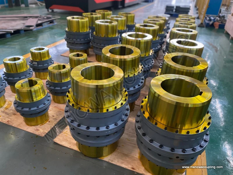
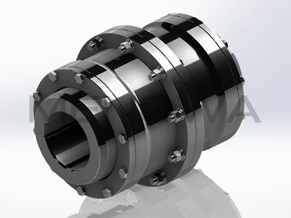
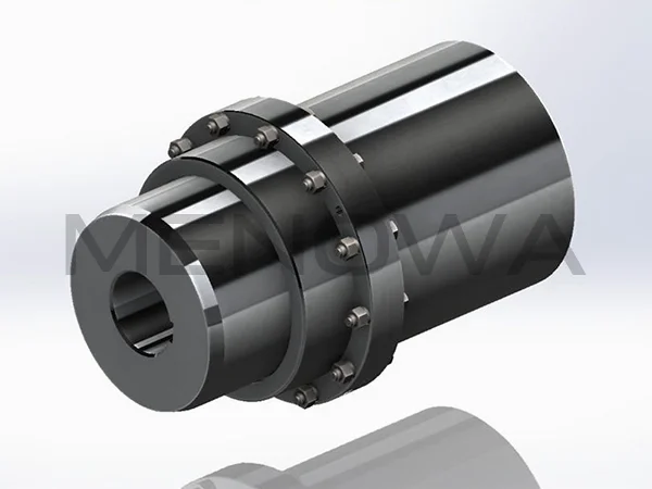
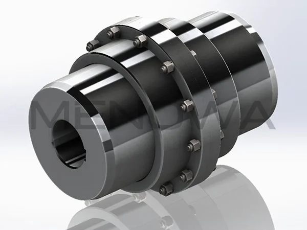
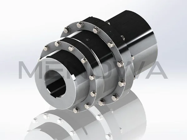
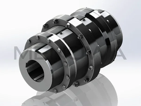
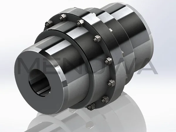
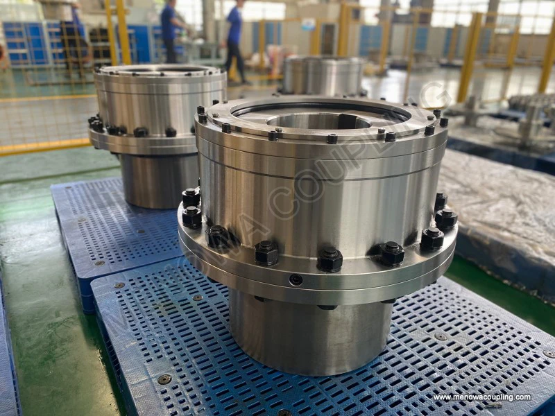
At its most basic level, the curved tooth coupling consists of two externally toothed hubs, each keyed and locked onto one of the two shafts to be connected, and a sleeve, sometimes called the outer hub or the internal ring, which carries internal teeth machined to engage with the teeth of both hubs simultaneously. The torque path is therefore straightforward: power enters through the first hub, is transferred across the meshing teeth into the sleeve, and is then passed across a second set of meshing teeth into the opposite hub and out through the second shaft. This gives the coupling a double set of engagements, and it is at these two interfaces that the characteristic flexibility of the unit is realised. The external teeth of the hubs are not cut as ordinary straight teeth with parallel flanks. Instead, each tooth is crowned, meaning that the tooth profile, viewed in the plane of the shaft axis, is machined with a curved or barrel-shaped surface whose highest point lies near the middle of the tooth flank and which falls away smoothly toward both ends. The tooth thus presents a convex surface to the internal tooth of the sleeve, and it is this deliberate crowning that constitutes the entire conceptual heart of the design.
The reason for crowning becomes clear when one considers what happens to a straight-toothed gear coupling under angular misalignment. If the two shafts are not perfectly collinear, the axes of the hubs are inclined to one another, and the teeth of one hub would, in an uncrowned design, attempt to engage the internal teeth of the sleeve at an angle. A straight tooth cannot tilt within its socket without the sharp edges of the tooth bearing hard against the edges of the sleeve tooth, concentrating the entire contact force on a very small strip of material at the extremity of the flank. This phenomenon is known in the trade as edge loading, and it is the principal enemy of coupling durability. Edge loading produces extremely high local contact stress, rapid wear of the tooth flanks, fretting of the contact surfaces, and premature fatigue failure of the tooth. The crowned tooth eliminates the problem by providing a curved surface that can rock gently within the internal tooth space. As the shafts take up an angular position, the crowned external tooth pivots about the highest point of its curve, and the line of contact between the mating teeth shifts across the crowned flank rather than concentrating at a single sharp edge. Because the contact is distributed over a meaningful portion of the tooth surface instead of being squeezed onto a thin edge, the contact stress remains manageable, and the coupling can transmit full torque even while the connected machinery operates with an angular offset that would rapidly destroy a straight-tooth unit.
The crowning also influences the nature of the contact itself. Under load, the crowned flank and the internal tooth establish a contact that is best described as a localized ellipse or a short band, the exact dimensions of which depend on the radius of the crown, the tooth curvature, the elastic properties of the material, and the magnitude of the transmitted load. As torque increases, the elastic deformation of the two surfaces flattens the theoretical point of contact into a small area, which is precisely the mechanism by which the coupling spreads the load across the material and avoids the point-loading that would cause immediate indentation or seizure. The design therefore offers a favourable trade-off: it sacrifices a small amount of theoretical tooth contact area in exchange for a dramatic improvement in the ability to carry load under misaligned conditions. In practice this means the curved tooth coupling can handle substantial angular misalignment, typically a small number of degrees, along with a modest degree of parallel offset and a limited amount of axial travel, all within a single compact envelope that occupies far less axial space than several other flexible designs of comparable torque rating.
The actual working principle can be stated precisely in terms of the kinematic behaviour of the tooth system. During rotation, the crowned teeth of the two hubs and the internal teeth of the sleeve form what is, in effect, an internal gear pair on either side of the unit. When the shafts are collinear, each tooth meshes with its counterpart across the full designed profile, and the coupling behaves almost as if it were rigid, transmitting motion with a very small and predictable angular displacement due to tooth backlash. When the shafts become misaligned, either because of installation error, thermal expansion of the machine casing, or deflection of the shafts under load, the crowned teeth accommodate the resulting angular difference by a rocking motion. The curved flank rolls relative to the internal tooth, and the meshing continues to transmit torque without the gear teeth separating or binding. It is important to recognise that this is not a sliding motion of one tooth past another in the direction of rotation, which would cause sliding wear, but rather a tilting of the tooth within its socket that preserves positive engagement. Because the contact surfaces are lubricated in service, a hydrodynamic or boundary oil film develops between the flanks, and this film both carries a portion of the normal load and prevents metal-to-metal contact that would otherwise accelerate wear and generate heat.
The ability of the coupling to accommodate misalignment is not unlimited, and the design carefully controls the geometry so that the crown radius, the tooth height, and the tooth clearance are matched to the intended misalignment capacity. If the misalignment exceeds the design value, the crown reaches the end of its useful travel, and further displacement would cause the tooth to bind against the ends of the sleeve teeth or to lose engagement altogether. For this reason the specified misalignment limits must be respected, and it is sound practice to align the machinery as closely as possible during installation, reserving the coupling's misalignment capability as a working allowance for operational deflection rather than as a substitute for reasonable alignment work. The angular capacity is the most important of the three allowances, because it is the angular error that most directly stresses the crowned teeth; parallel offset and axial displacement, while also accommodated, place different demands on the unit and are generally more forgiving in terms of tooth loading.
Selecting a curved tooth coupling for a given application is a disciplined exercise in matching the capacity of the unit to the demands of the driven and driving machines, and the first and most fundamental quantity to be established is the torque that the coupling must transmit. In metric practice the torque is calculated from the transmitted power and the shaft speed using the familiar relation T equals 9550 multiplied by P and divided by n, where T is the torque in newton-metres, P is the power in kilowatts, and n is the rotational speed in revolutions per minute. In imperial units the equivalent expression is T equals 5252 multiplied by horsepower and divided by rpm, giving torque in pound-feet. This calculated value represents the nominal, or steady, torque delivered by the prime mover under normal operating conditions, but it is not, on its own, sufficient for selecting a coupling, because the real torque experienced by the coupling in service is almost always higher than the nominal figure.
The actual design torque is obtained by multiplying the nominal torque by a service factor that accounts for the severity of the application. The design torque T subscript c equals the nominal torque T multiplied by the service factor K, and the coupling is then chosen such that its rated torque capacity is equal to or greater than this design torque. The service factor is not a single universal number but depends on several characteristics of the driven load: whether the load is steady, such as a constant-speed fan, or subject to heavy shock, such as a reciprocating compressor or a rolling mill; the inertia of the driven machine and the frequency with which it is started and stopped; the presence of reversing torques, fluctuating loads, or torque peaks caused by process irregularities; and the number of hours per day the equipment operates. A smooth, continuously operating load with a centrifugal driver might justify a modest service factor, whereas a high-inertia, shock-loaded machine with frequent reversals demands a substantially higher factor. The selection engineer multiplies the two values together and then reviews the resulting design torque against the coupling catalogue, taking care also to verify that the selected unit can operate at the required speed, since very high speeds impose their own limitations related to the balance of the rotating assembly and the behaviour of the lubricant under centrifugal force.
Beyond torque and speed, the selection process must address the physical and spatial constraints of the installation. The bore sizes of the two hubs must accommodate the shaft diameters, and the hubs must be suitable for the method of mounting, whether by keyway, by interference fit, or by other locking means. The overall length and outside diameter of the coupling must fit within the available space on the shaft and within any guarding or housing, and the designer must confirm that the coupling can be assembled, aligned, and disassembled with the tools and access available on site. The required misalignment capacity of the application must be compared with the coupling's rated angular, parallel, and axial allowances, and where the machinery is known to deflect under load, it is prudent to leave margin beyond the nominal operating misalignment. The lubrication arrangement is a further consideration, because the curved tooth coupling depends on a supply of clean lubricant to the tooth mesh, whether by a sealed grease-packed unit that is periodically re-lubricated or by a continuous oil feed in high-speed or high-duty installations. The choice of lubricant, the relubrication interval, and the provision for venting and draining all affect the reliability and life of the unit, and they should be decided at the design stage rather than left to chance in service.
The working principle and the selection discipline are brought together in the range of applications that the curved tooth coupling serves. Because the design offers a high torque capacity in a compact axial length while tolerating misalignment, it is found in the heaviest categories of rotating machinery. Rolling mills and metal-forming equipment rely on it to transmit the very large torques of the mill drives while accommodating the deflections and thermal growth of the mill housings. Cement plants use it on kiln drives, mills, and bucket elevators where long shafts and heavy loads are common. Mining and bulk-handling conveyors, crushers, and screens transmit substantial power through curved tooth couplings that accept the shock loads and misalignment typical of these installations. Compressors and pumps in the oil, gas, and process industries are frequently connected through crowned tooth couplings, which provide the necessary flexibility and torque transfer for both driver and driven machines. Power generation, including turbine-driven and diesel-driven sets, takes advantage of the coupling's high-speed capability and its tolerance of thermal and torsional effects. Marine propulsion and auxiliary drives, cranes, hoists, mixers, agitators, and many other items of heavy mechanical plant all find a natural fit for the curved tooth coupling, which has earned its reputation over decades of service in exactly the environments where a failure is most costly and where reliability is at a premium.
The long service life that makes the coupling attractive in these demanding roles is not automatic; it depends on correct installation, accurate alignment, and disciplined maintenance. The coupling should be installed so that the initial misalignment is as small as practicable, with the rated allowances held in reserve for operational deflection. The teeth must be lubricated according to the manufacturer's guidance, and the condition of the teeth and the amount of backlash should be inspected periodically, because an increase in backlash or visible wear of the crowned flanks is an early indication that the misalignment is excessive or that lubrication has been neglected. In a sealed unit, attention to the re-lubrication interval and to the condition of the sealing elements preserves the integrity of the lubricant charge, while in an oil-lubricated unit the flow, cleanliness, and viscosity of the oil are the controlling factors. A curved tooth coupling that is well aligned, correctly lubricated, and loaded within its rated capacity will typically give years of trouble-free service, and its predictability is one of the reasons engineers continue to specify it wherever power must be transmitted reliably across a rotating joint.
In summary, the working principle of the curved tooth coupling rests on a single elegant idea: by crowning the external teeth of the hubs, the designer converts the tooth surfaces into curved bearing surfaces that can tolerate angular displacement without the destructive edge loading that would destroy a straight-tooth gear coupling. The crowned teeth maintain positive engagement across a distributed contact area, a lubricated film protects the flanks, and the result is a coupling that transmits high torque within a compact envelope while accepting the misalignment that real machinery inevitably presents. Correct selection, grounded in the calculation of nominal torque from power and speed, the application of an appropriate service factor, and a careful review of bore sizes, speed capability, misalignment allowances, and lubrication arrangements, ensures that the coupling is neither under- nor over-sized for its duty. Used within its rated limits and maintained with reasonable care, the curved tooth coupling delivers the combination of capacity, compactness, and reliability that has made it a standard solution in the heaviest and most demanding sectors of the international machine-building and process industries.
Post Date: Oct 13, 2026
https://www.menowacoupling.com/china-coupling/working-principle-of-curved-tooth-coupling.html
Products
Tags
Supply
Related Articles
Gear Type Coupling Fabrication
Gear type coupling fabrication is a sophisticated and systematic manufacturing process focused on producing robust, flexible mechanical transmission components that connect rotating shafts to transmit torque while accommodating minor axial, radial, and angular misalignments. As a core component in mechanical transmissio…Maintenance of Gear Type Coupling
Gear type couplings serve as indispensable mechanical transmission components in industrial mechanical systems, widely applied in shaft connection scenarios of various rotating equipment to transmit torque, compensate for minor shaft displacement deviations, and buffer mechanical vibration generated during equipment ope…Working Principle of Gear Type Coupling
A gear type coupling is a mechanical device specifically designed to connect two rotating shafts, enabling the efficient transmission of torque and rotational motion while accommodating a certain degree of misalignment between the shafts. Unlike rigid couplings that require precise alignment to function properly, gear t…Barrel Gear Coupling Sleeves
Barrel gear coupling sleeves stand as essential structural and functional components within modern mechanical power transmission systems, serving as the central connecting medium that bridges driving and driven shafts across a vast range of industrial machinery and rotating equipment. In every mechanical setup that reli…Structure of Curved Tooth Coupling
Curved tooth couplings, which are also widely referred to as crowned tooth gear couplings, occupy a distinctive position in the field of mechanical power transmission and have earned a steadily expanding share of the international market. Their appeal rests on a rare combination of high torque capacity, generous toleran…Diagram of Curved Tooth Coupling
The diagram of curved tooth coupling intuitively presents the structural layout, meshing logic and spatial assembly relationship of this mainstream flexible transmission component, serving as a core technical reference for design optimization, model selection, installation and maintenance in the global industrial machin…
 WeChat
 WhatsApp