Structure of Curved Tooth Coupling
Curved tooth couplings, which are also widely referred to as crowned tooth gear couplings, occupy a distinctive position in the field of mechanical power transmission and have earned a steadily expanding share of the international market. Their appeal rests on a rare combination of high torque capacity, generous tolerance for shaft misalignment, and long, predictable service life, and they are now specified across industries that range from heavy steelmaking to high-speed turbomachinery. Understanding the internal structure of such a coupling is the foundation for proper selection, installation, and maintenance, and it is equally important for engineers who supply, specify, or procure these components in cross-border projects, because the mechanical logic of the crowned tooth is what ultimately determines how much misalignment the coupling can absorb, how much torque it can carry, and how long it will remain trouble-free in service.
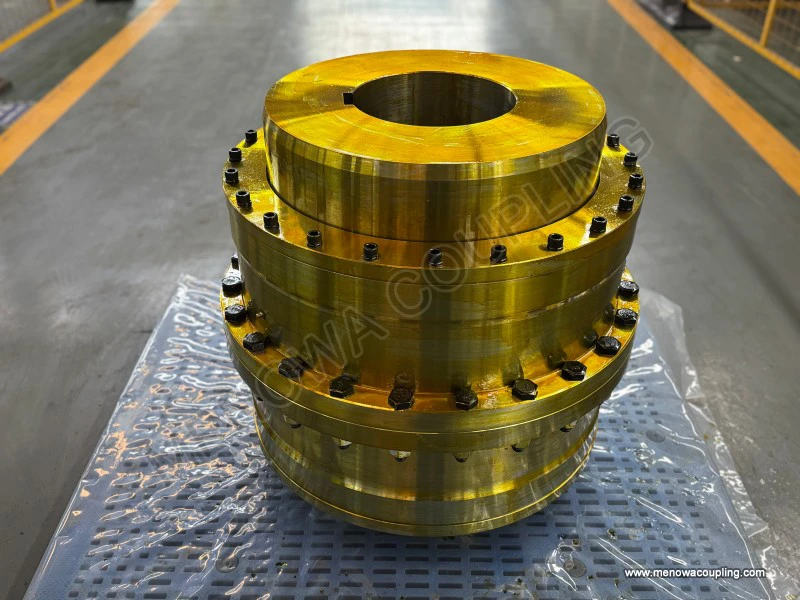
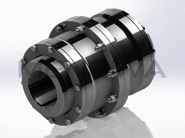
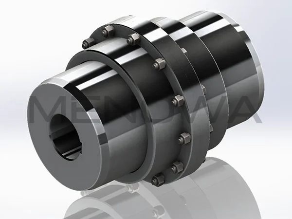
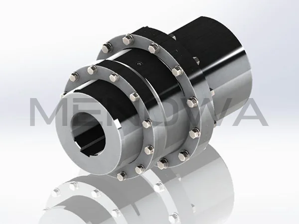
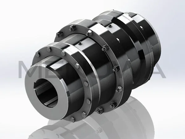
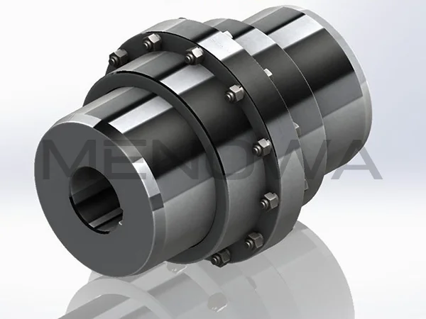
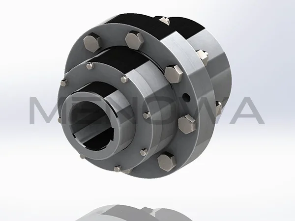
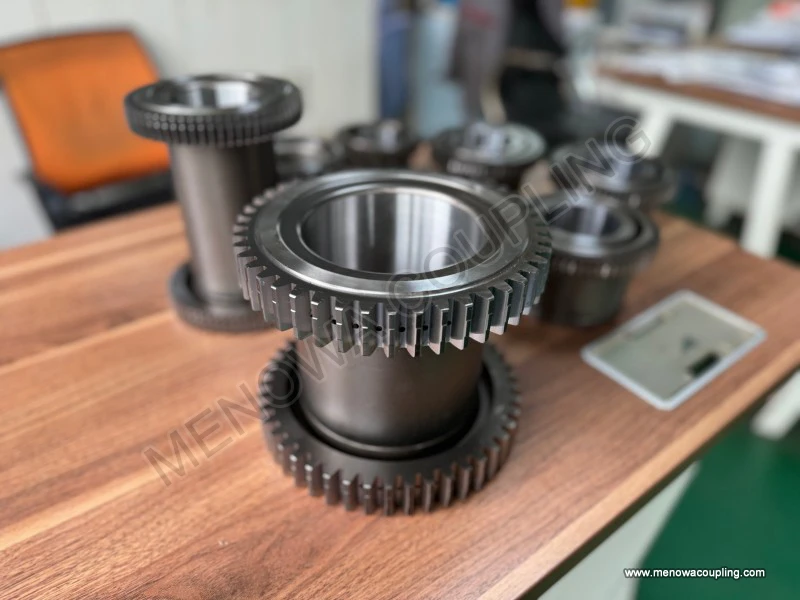
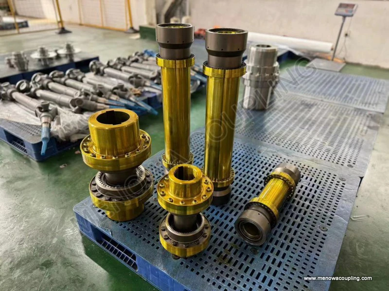
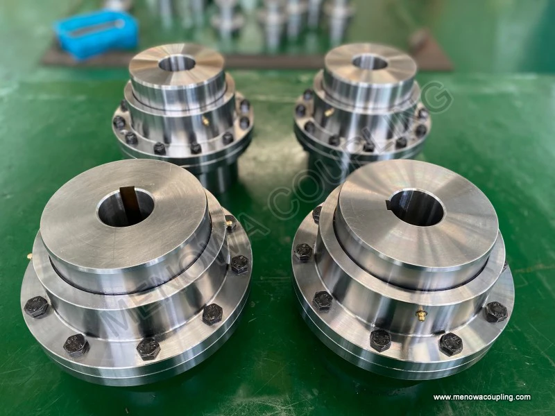
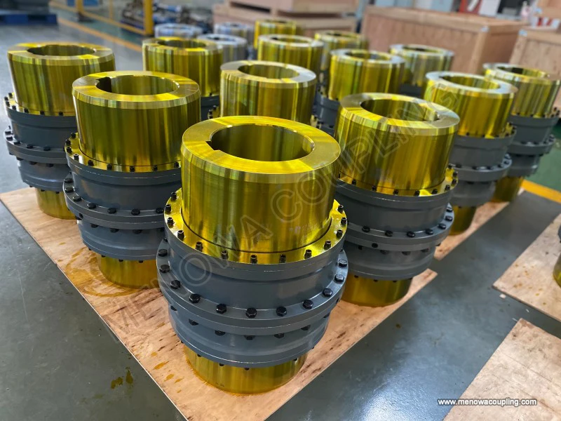
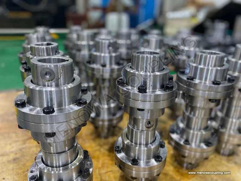
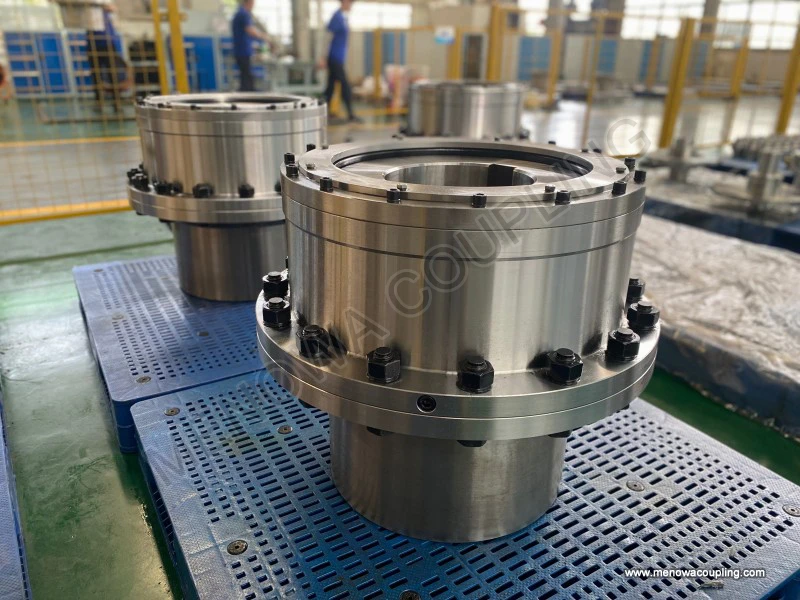
The structure of a curved tooth coupling is deceptively simple in appearance but carefully engineered in detail. In its most common double-engagement form, the assembly consists of two separate hubs, two flanged outer sleeves, and a set of connecting bolts that clamp the two sleeve flanges together. Each hub is machined with external gear teeth and is bored to accept the shaft end of the driven or driving machine, being fixed to the shaft by a key, a taper lock arrangement, or an interference fit depending on the duty and the designer's preference. Each outer sleeve carries internal gear teeth that mesh with the external teeth of its mating hub, and the two sleeves are bolted flange to flange so that torque passes from the driving hub through its sleeve, across the bolted joint, and into the second sleeve and hub on the driven side. Between the two meshing gear pairs, the coupling is able to accommodate angular misalignment, parallel offset, and axial movement, because each gear mesh behaves like a pivot that allows a small angular deflection between the axis of the hub and the axis of the sleeve.
The defining feature of the curved tooth coupling is the longitudinal profile of the external teeth. Instead of being straight-sided along the length of the tooth, the teeth are machined with a crowned, or curved, profile, meaning that the tooth flank is slightly convex when viewed in the axial direction, so that the tooth is highest at its midpoint and tapers gently toward both ends. This crown radius is not an incidental manufacturing detail; it is the heart of the coupling's flexibility. When the two shafts are angularly misaligned, the crowned teeth roll and slide relative to the internal teeth of the sleeve instead of jamming against them, and the contact area shifts along the tooth length in a controlled manner. The result is that the crowned profile converts what would otherwise be severe edge loading into a smoother, more distributed contact, and it allows the coupling to operate through a considerably larger angle than a straight-toothed gear coupling of the same size. In practice a single curved tooth mesh can typically handle an angular deflection of up to one and a half to two and a half degrees, and because a standard coupling contains two meshes, the total angular capability can reach three to five degrees in a double-engagement arrangement, a figure that is a multiple of what conventional gear couplings can tolerate.
This structural arrangement delivers several operating advantages that explain the coupling's strong position in the global market. The crowned teeth maintain continuous contact across the mesh, so torque is transmitted through many teeth simultaneously, which spreads the load and reduces the peak stress on any single tooth. Because the coupling does not rely on elastic elements such as rubber bushes or metallic springs, it can transmit very high torque in a relatively compact envelope, which makes it attractive in applications where space is limited and reliability is paramount. The absence of wearing elastomeric inserts also means that the coupling can operate at higher temperatures than flexible couplings that depend on rubber or polyurethane elements, and it is far less sensitive to oil, grease, and process contamination in many industrial environments. These properties have made the curved tooth coupling the workhorse of the heavy end of power transmission, where downtime is costly and where the consequences of a coupling failure are severe.
The international demand for curved tooth couplings is closely tied to the growth of capital-intensive process industries and the steady expansion of infrastructure in developing economies. Steel rolling mills are among the most prominent users, because the drives that power the work rolls must transmit enormous torque while tolerating the unavoidable misalignment that arises from thermal expansion, foundation settlement, and the bending of long mill housings. Continuous casting machines, hot and cold strip mills, and finishing trains all rely on crowned tooth couplings at critical points in the drive train. The cement industry is another major consumer, where the large gearboxes that turn kilns and ball mills are driven through couplings that must handle high torque, moderate misalignment, and the dust-laden atmospheres typical of crushing and grinding plants. The mining and minerals sector applies the same coupling in conveyors, crushers, mills, and slurry pumps, often in remote locations where maintenance access is difficult and where the extended life of the coupling is a decisive economic factor. Power generation plants use these couplings on boiler feed pumps, cooling tower fans, condensate pumps, and auxiliary drives, while the oil and gas sector applies them on compressors, pumps, and generator sets both onshore and offshore. Beyond these heavy industries, curved tooth couplings appear in paper mills, sugar mills, marine propulsion and deck machinery, material handling systems, and large ventilation and air-handling installations. In every one of these settings, the common thread is a need for reliable torque transmission combined with a realistic tolerance for the misalignment that real machines and real foundations produce.
When an engineer approaches the selection of a curved tooth coupling for an international application, the process begins with a precise definition of the duty. The first step is to establish the operating torque, which is derived from the transmitted power and the rotational speed. In the widely used system of units where power is expressed in kilowatts and speed in revolutions per minute, the nominal torque in newton-metres is given by the familiar relationship where the torque equals 9550 multiplied by the power and divided by the speed. This nominal torque represents the steady-state requirement, but it is rarely the value on which the coupling is chosen, because real machinery is subject to starting surges, shock loads, and periodic fluctuations that can exceed the average torque several times over.
To account for these transient conditions, the design torque is obtained by multiplying the nominal torque by a service factor that reflects the nature of the load and the duty cycle. The service factor is not a fixed universal number; it is chosen by the engineer based on the type of prime mover, the characteristics of the driven machine, the frequency of starting, and the presence or absence of shock. For a smooth, continuously operating load driven by an electric motor, a modest service factor may suffice, while for a reciprocating compressor, a crusher, or a mill that experiences severe shock and frequent reversals, a substantially higher factor is required. The selection rule then reduces to a single condition: the rated torque capacity of the chosen coupling, as stated by its manufacturer for the relevant speed, must be equal to or greater than the design torque. In equation form, the designer first computes the nominal torque from the power and speed, then multiplies by the chosen service factor to obtain the design torque, and finally selects a coupling whose rated capacity at the operating speed at least equals the design torque.
Speed enters the selection process in a second way, because the allowable torque of a gear coupling is not constant across the speed range. As the pitch-line velocity of the teeth rises, centrifugal effects, lubrication behavior, and dynamic loading begin to influence the capacity of the mesh, and most manufacturers derate the torque rating progressively at higher speeds. The engineer must therefore check the coupling at the actual operating speed, not merely at the nominal rating, and must confirm that the permissible speed of the coupling exceeds the maximum speed the machine can reach. For high-speed applications the pitch-line velocity of the gear teeth, which is the product of the pitch diameter and the rotational speed, becomes a meaningful design parameter, and the lubrication system must be capable of maintaining an adequate film under the prevailing centrifugal conditions.
Beyond torque and speed, a complete selection exercise must verify that the coupling can accommodate the misalignment that will actually occur between the two shafts. The required angular misalignment, the parallel offset, and the axial movement are estimated from the machine train layout, the thermal growth of the components, and the manufacturing tolerances of the foundation and the bearings, and each must be compared with the capacity of the coupling as published by the manufacturer. It is a common mistake to assume that because a coupling can absorb several degrees when new, it will operate happily at that limit indefinitely. In reality, continuous operation at the maximum misalignment accelerates wear of the crowned teeth, increases the transmitted bending moment on the shafts and bearings, and shortens the life of the coupling, so the prudent designer allows a comfortable margin between the expected misalignment and the rated maximum. The bores of the hubs must also be checked against the shaft diameters and the required keyway dimensions, and the axial float of the coupling must be sufficient to absorb the thermal expansion of the shafts without transmitting harmful thrust loads to the bearings.
The curved tooth geometry also imposes some practical considerations on the teeth themselves that influence both selection and longevity. The curvature of the crowned teeth is optimized for a particular range of angular deflection, and the pressure angle and the amount of crown are chosen together to balance load-carrying capacity against flexibility. A deeper crown increases the permissible angle but reduces the length of tooth in contact at maximum deflection, so the tooth surface pressure rises, and the allowable torque at the misalignment limit is correspondingly lower. This trade-off means that the rated torque of a curved tooth coupling is not an absolute figure; it depends on the angle at which the coupling is expected to operate, and many manufacturers publish their torque ratings on the understanding that the coupling will run at a relatively small misalignment, with the full angular capacity reserved for installation tolerance and occasional excursions rather than for continuous service.
The material and heat treatment of the teeth deserve close attention in international procurement because they largely determine the wear life of the coupling. The hubs and sleeves are usually manufactured from forged or rolled alloy steel, and the gear teeth are frequently hardened, either through induction hardening of the tooth flanks or through a full heat treatment of the component, so that the contacting surfaces are hard enough to resist pitting and wear while the body of the part retains sufficient toughness to absorb shock. The quality of the tooth flank finish and the accuracy of the gear geometry directly influence the smoothness of engagement and the noise level of the coupling, and in high-speed applications a poorly finished tooth flank can generate unacceptable vibration. The internal tooth form of the sleeve is typically finished by broaching or shaping, and the crowned external teeth are produced by generating processes that impart the required longitudinal curvature with the necessary accuracy.
Lubrication is inseparable from the successful operation of a curved tooth coupling, and the design of the coupling reflects this requirement. The internal cavity that contains the meshing teeth is filled with a suitable grease or, in high-speed or high-temperature duty, is supplied with a continuous oil flow, and the assembly is sealed at its ends by closures that retain the lubricant and exclude contaminants. The type and grade of lubricant are selected for the operating temperature and the rotational speed, because the centrifugal field at high speed tends to throw the lubricant to the outer wall of the cavity, and the formulation must continue to protect the tooth contact under these conditions. The frequency of re-lubrication depends on the duty, and the maintenance schedule of the plant must reflect it, because a starved mesh is the most common cause of premature wear in crowned tooth couplings.
Installation quality has a direct and measurable effect on the life of the coupling. The alignment of the two shafts should be set as close to zero as practical, and the angular and parallel misalignment should be measured with proper instruments and recorded, because the actual operating misalignment, not the rated maximum, determines the wear rate of the teeth. The bolted flange joint must be assembled with the correct tightening sequence and torque so that the two sleeves are clamped firmly together and the load is shared evenly across the flange. The hubs must be fixed securely to their shafts, and the axial position of each hub must allow the coupling to accommodate the expected axial float without binding. In many installations the coupling is initially assembled, aligned, and run-in before being brought to full speed and load, and the initial running-in period is an opportunity to confirm that the coupling is operating smoothly and that the temperature of the housing remains within the normal range.
The international market for curved tooth couplings is shaped by several broad trends that the procurement engineer should keep in mind. There is a continuing movement toward higher torque density, driven by the desire to reduce the size and weight of drive trains and to lower the cost of the enclosing machinery, and this has encouraged the development of compact high-capacity couplings that can deliver a given torque in a smaller package. There is also growing attention to total cost of ownership rather than first cost, because the downtime and maintenance expense associated with a coupling failure far exceed the initial purchase price, and this favors couplings with long life, good sealing, and easy re-lubrication. The globalization of manufacturing has led to a convergence of dimensional and rating practices across regions, so that a coupling designed for the requirements of one market is increasingly expected to be acceptable in another, and cross-border projects frequently demand that a coupling be selected against a set of internationally recognized engineering practices rather than a single local tradition.
The selection of the correct curved tooth coupling for an international application therefore demands attention to the real conditions of the machine train, including the torque at the actual operating point, the service factor that reflects the true nature of the load, the speed and the pitch-line velocity, the misalignment that will actually be present, the bore sizes and axial float, the temperature and environment of the installation, and the lubrication and maintenance that the plant can realistically provide. Each of these parameters influences the final choice, and none of them can be safely ignored. The nominal torque is computed from the power and the speed, the design torque is obtained by applying the service factor, and the coupling is then selected so that its rated capacity at the operating speed exceeds the design torque with a suitable margin, while the angular, parallel, and axial capabilities are verified against the expected values and the tooth contact pressure is checked at the intended operating angle.
The curved tooth coupling is, in essence, a precisely engineered compromise between the desire for high torque capacity and the unavoidable reality of misalignment, and its structure reflects that compromise in every crowned tooth. Its continued popularity in the international market is well deserved, because when it is selected correctly, installed with care, and lubricated and maintained according to the manufacturer's instructions, it provides a level of reliability and service life that few other flexible couplings can match in the heavy and demanding applications for which it is designed. The engineer who understands the structure of the crowned tooth, the reasons for its shape, and the way that shape interacts with torque, speed, and misalignment is far better equipped to choose a coupling that will perform reliably for years, and to diagnose and prevent the problems that account for most coupling failures in the field. In an era when production continuity and predictable maintenance are decisive competitive advantages across every industrial region, the humble crowned tooth remains one of the most effective and trusted instruments of reliable power transmission available to the international engineering community.
Post Date: Oct 13, 2026
https://www.menowacoupling.com/china-coupling/structure-of-curved-tooth-coupling.html
Products
Tags
Supply
Related Articles
Uses of Curved Tooth Coupling
The curved tooth coupling, also known as a crown gear coupling or a curved-tooth gear coupling, has established itself as one of the most dependable components in heavy-duty power transmission across global industry. While flexible couplings exist in many forms, the curved tooth design distinguishes itself through an ex…Gap Chart of Curved Tooth Coupling
Global industrial transformation across manufacturing, energy exploitation, heavy engineering and marine equipment has steadily lifted market demand for curved tooth coupling in cross-continental industrial supply chains over recent years, with gap chart becoming an indispensable technical reference for product matching…Gear Type Coupling Price
Gear type couplings stand as one of the most versatile and widely adopted mechanical transmission components in modern industrial machinery, serving as a critical link between rotating shafts to ensure stable torque transfer while accommodating unavoidable shaft deviations during equipment operation. Unlike rigid coupli…Specification of Gear Type Coupling
Gear type coupling is a widely adopted rigid-flexible transmission component in mechanical power transmission systems, designed primarily to connect two rotating shafts for continuous torque transmission while absorbing and compensating for various shaft misalignments generated during equipment operation. Its core worki…Classification of Gear Type Coupling
Gear type couplings are essential mechanical transmission components widely applied in industrial mechanical systems, serving the core function of connecting two rotating shafts to transmit torque and rotational motion while compensating for various installation and operation deviations between shafts. Compared with oth…What is Curved Tooth Coupling
A curved tooth coupling is a mechanical device used to connect two rotating shafts so that torque and rotation can be transmitted from a driving machine to a driven machine while accommodating small amounts of misalignment between them. It belongs to the family of flexible couplings, and it is distinguished from simpler…
 WeChat
 WhatsApp