Types of Curved Tooth Coupling
A curved tooth coupling, often described as a crowned tooth gear coupling, is one of the most widely used flexible couplings in heavy industry, and it earned that position for a simple reason: it combines exceptionally high torque capacity with a genuine ability to absorb the misalignments that always appear between real rotating shafts. Machinery is never built, erected and operated in a state of perfect alignment. Foundations settle, steel structures distort under load and temperature, bearings wear, and long shaft lines flex. A rigid coupling would transmit every one of those errors directly into the bearings and shafts, while a soft elastomeric coupling would survive the misalignment but fail under the torque. The curved tooth coupling sits between these extremes, transmitting torque through positive steel to steel meshing teeth while still allowing the coupled shafts to rock, offset and slide relative to one another within defined limits. That combination is why the type dominates in mills, crushers, turbines, pumps and the other demanding drives where most other flexible couplings wear out or break early.
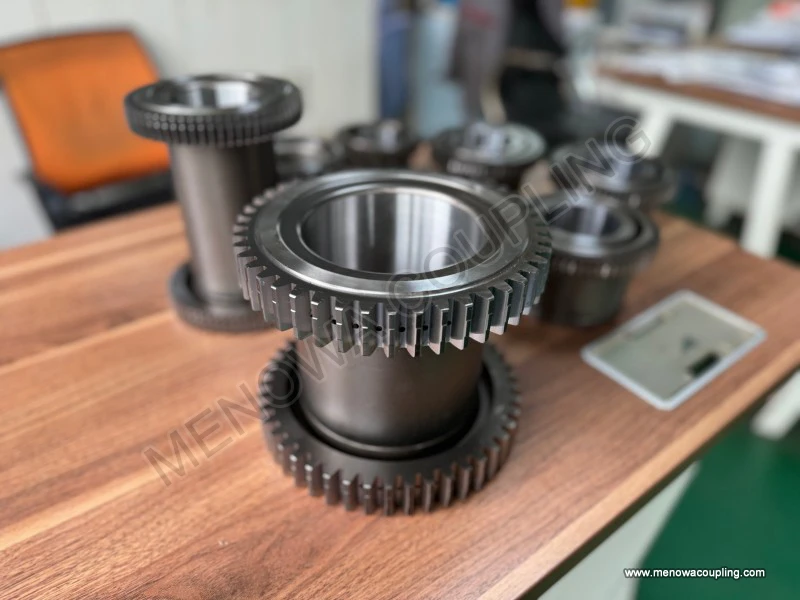
The principle that makes this possible is a subtle change to the tooth geometry. In a straight tooth gear coupling the external teeth are generated as a true involute form, and the two sets of teeth are designed to mesh with their axes almost exactly aligned. Under any meaningful misalignment the straight teeth bind at their edges, concentrate the whole load on a tiny contact point, wear quickly and eventually fail. A curved tooth coupling instead shapes the outer teeth along their length as a spherical or barrel-like crown, with the crown radius centred on the shaft axis. Because the tooth flank is curved rather than flat, the mesh can rock and slide against the internal teeth while still keeping contact across a useful portion of the flank. The curved profile eliminates the damaging edge contact, spreads the stress over a larger area, reduces friction and wear, lowers vibration and allows the teeth to compensate for angular misalignment, parallel offset and axial movement that would be impossible for a straight tooth design. The clearance between the mating teeth is deliberately generous, and this clearance, together with the crown, is what lets the meshing teeth slide and rock instead of binding. It is worth emphasising that in normal operation there is no relative rotation between the two sets of teeth as there is in an ordinary gear set; the coupling is transmitting torque, and the teeth simply roll and slide over a small angular range to accommodate shaft movement.
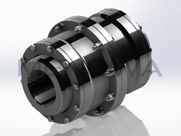
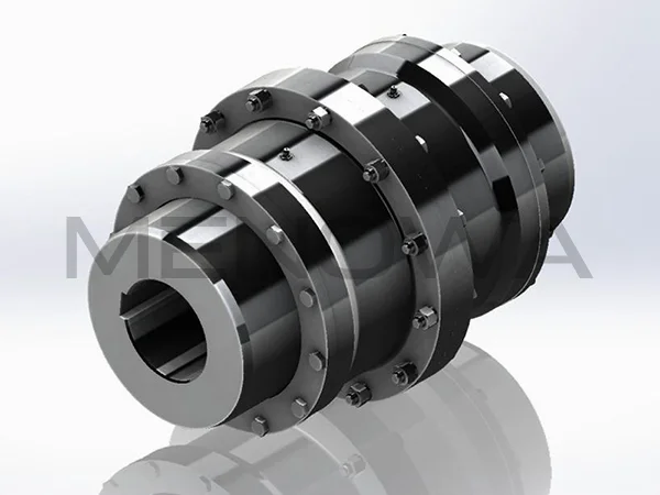
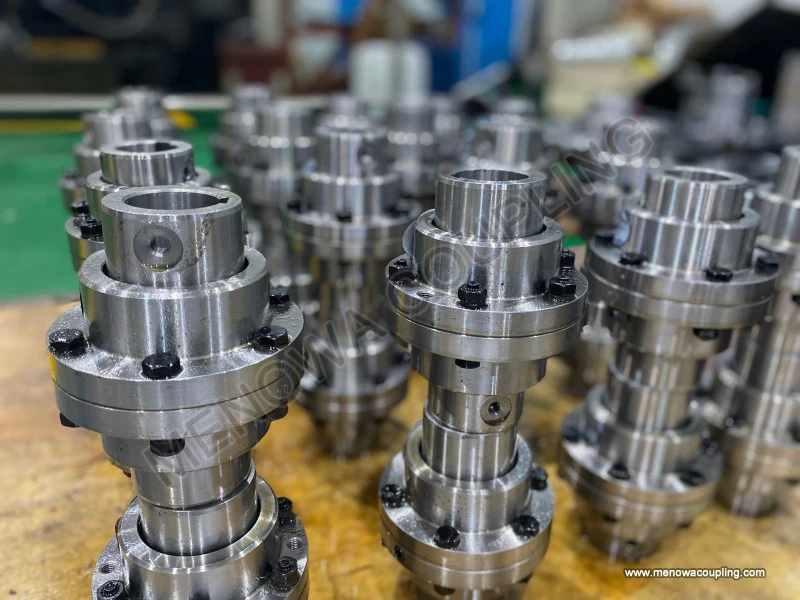
Understanding the types of curved tooth coupling is the essential first step in correct selection, because the differences between them are functional rather than cosmetic. The most fundamental distinction is between the single engagement and the double engagement configuration. A single engagement curved tooth coupling has one set of meshing teeth between the driving hub and a sleeve, which gives it one plane of articulation; it compensates for angular misalignment of the two shaft axes but cannot accept a parallel offset, because with only a single mesh there is no way for the two centres to be displaced sideways. A double engagement version places a floating intermediate sleeve between two crowned tooth meshes, effectively giving the coupling two articulating joints. That configuration absorbs angular misalignment, parallel shaft offset and any combination of the two, which is why double engagement units are the everyday choice for most coupled drives. The two mesh design also halves the tooth load carried in each mesh for a given torque, which can materially extend service life in high load applications even though the coupling is longer and slightly heavier. A designer who needs to absorb only angular misalignment, and has no parallel offset in the machine, can legitimately choose the lighter single engagement form; a long line shaft or a drive where the two machines sit on different foundations almost always needs double engagement.
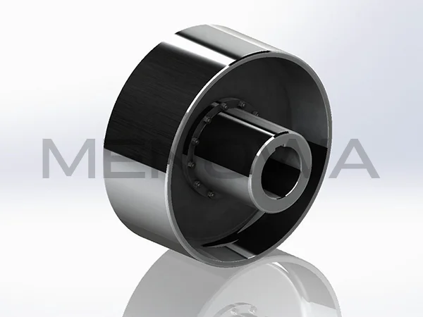
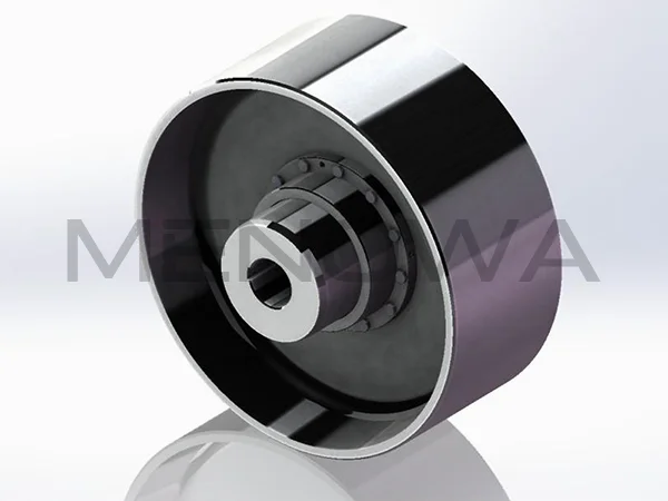
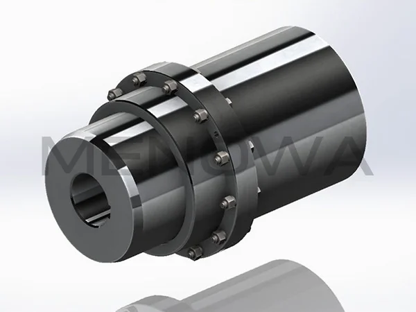
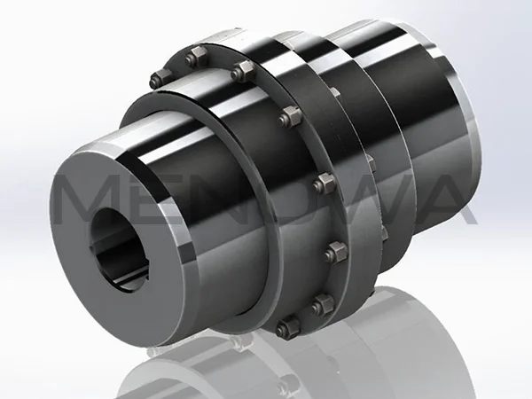
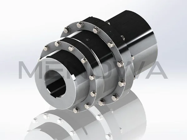
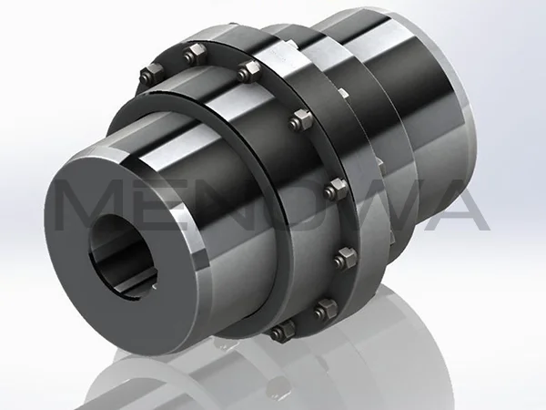
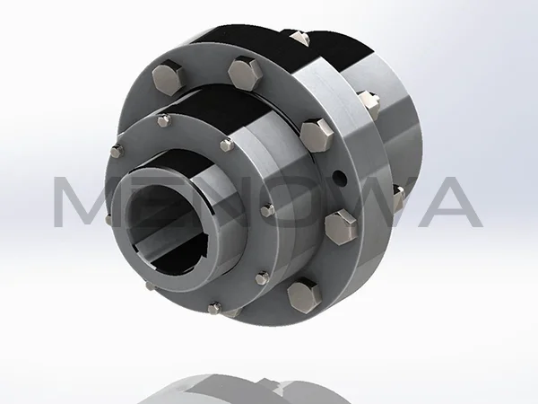
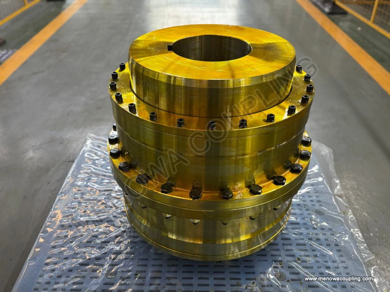
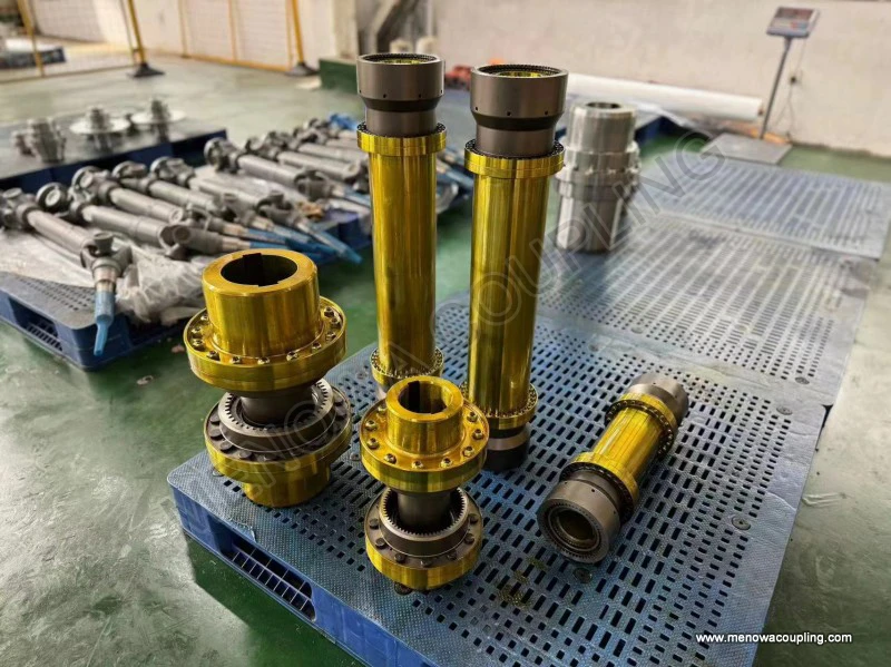
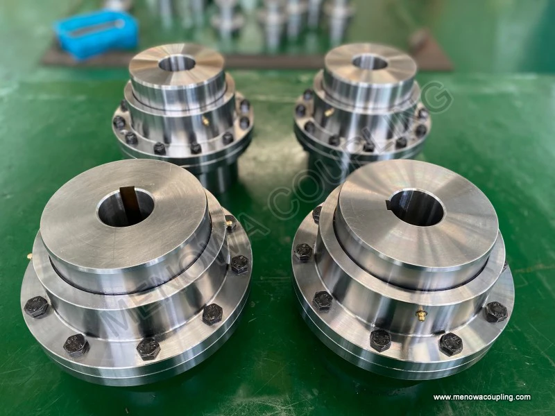
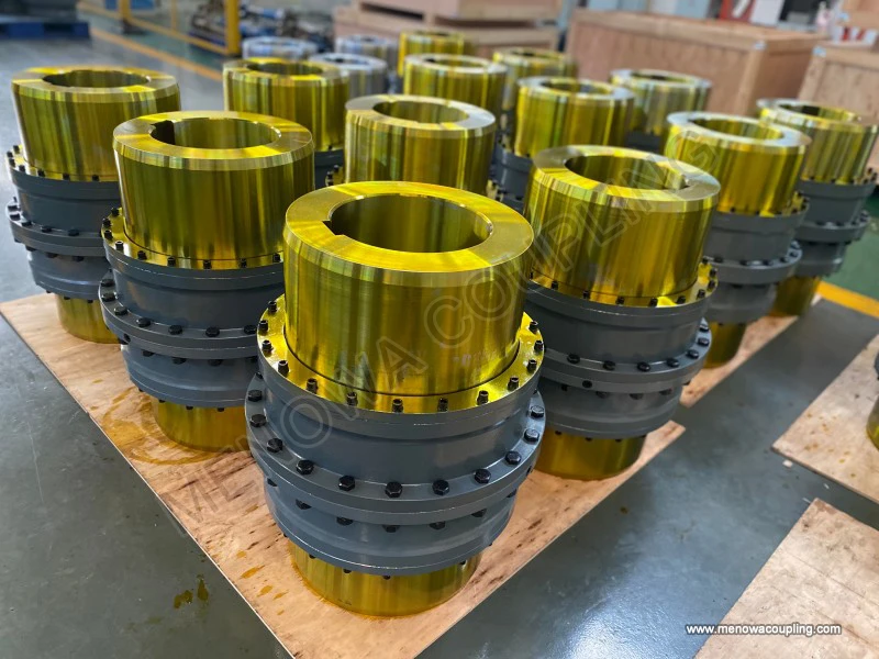
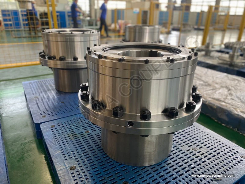
The same meshing geometry is then built into several mechanical arrangements that differ mainly in how they connect to the shafts. The flange type is the most common: each half consists of a hub bored and keyed to its shaft, and a flanged sleeve that is bolted to the mating half. Flange couplings are robust, easy to dismantle and ideal for large bores and high torques, but they are long and need generous space to withdraw the bolts during maintenance. The continuous sleeve type is a single piece into which both hubs are inserted, with the whole assembly held together by set screws or clamp rings; it is shorter, cheaper and more compact, which makes it attractive for close coupled machines, but it is harder to remove from the shaft and offers less room for large bore sizes. For quick mounting and remounting, clamp type hubs with split bores and radial screws are popular because they grip the shaft without end thrust and can be released without disturbing the machine. Where the drive must be positive and nearly free of backlash, a splined or tapered bore connection is preferred over a simple keyway, and for very large shafts a hydraulically fitted or shrink disc connection can transmit the highest torques without fretting.
A further distinction concerns the shape of the crown itself. Some designs use a single curvature crown, in which the tooth flank curves in only one direction, while others use a double curvature or fully barrel shaped profile that curves in both directions along the tooth. The double curvature form reduces edge contact further and distributes stress more evenly across the flank, which lowers friction, limits wear and cuts vibration, at the cost of a slightly reduced load capacity per unit of face width. A related option is the partially crowned tooth, in which only a portion of the face is crowned, which suits applications where the anticipated misalignment is small but the torque is very high. Manufacturers of the type normally state the allowable angular misalignment per mesh in degrees, and typical crowned tooth couplings accept on the order of one to one and a half degrees of angular misalignment per mesh; double engagement units combine the two meshes to handle parallel offsets of several millimetres and combined angular conditions that straight tooth units cannot tolerate at all. Where the two coupled shafts must also be allowed to float axially, because of thermal expansion, a floating sleeve permits a defined amount of end float, and this must be checked against the machine's actual axial movement before the unit is sized, because exceeding the float limit will drive the teeth hard against their end stops.
The choice of a curved tooth coupling for a given drive is made by a methodical selection procedure that begins with torque, not with size. The nominal torque transmitted is calculated from the drive power and the operating speed using the standard relationship T = 9550 × P / n, where T is the nominal torque in newton metres, P is the transmitted power in kilowatts and n is the shaft speed in revolutions per minute; the constant 9550 is simply 60000 divided by 2π and converts the power and speed into newton metres. This figure, however, represents only the steady running torque and does not reflect the shock loads, starting torque, reversing stresses or load variation that real machinery produces. The coupling is therefore selected on a design torque obtained by multiplying the nominal torque by a service factor, so that Tdesign = K × 9550 × P / n, where K is a dimensionless factor chosen according to the type of prime mover and the driven machine. For a smooth, constant load such as a uniform blower driven by an electric motor, a service factor of the order of 1.2 to 1.5 may be sufficient, whereas a reciprocating compressor, a reversing rolling mill, a crusher or a punch press demands factors of 2.0, 2.5 or even 3.0 because of the violent torque peaks and shock loading they impose. Once the design torque is known, the designer chooses a coupling size whose rated torque capacity equals or exceeds that value, using the rated capacities published for each frame size, and then confirms that every other constraint is satisfied.
Torque is only the first gate in the selection, and a coupling that passes it can still fail if the other constraints are ignored. Speed must be checked against the coupling's maximum permissible speed, because above a certain peripheral velocity of the tooth tips the lubricant is thrown off and the teeth begin to wear rapidly and generate heat; high speed units are therefore usually supplied with a sealed oil reservoir or specially shaped teeth and may require balancing, whereas low speed, high torque drives are more tolerant. The bore capacity of the coupling must be large enough to accept the shaft diameters, and the hub bore, keyway or clamping system must be matched to the shaft fit so that no fretting occurs under reversing load. Misalignment capacity must be compared with the measured or expected misalignment at installation, always remembering that the coupling is never to be used as an excuse for poor alignment but rather as a safety margin for residual error and for the thermal and foundation movement that occurs in service; the accepted practice is to align the machine as well as practical and to treat the coupling's misalignment rating as spare capacity rather than as a permitted running condition. The required axial float must be confirmed against the catalogue float of the chosen unit. Temperature must be considered, because at elevated service temperatures standard seals and lubricants degrade, and special high temperature greases, metallic seals or forced oil circulation may be needed; conversely, in cold climates a grease that is too stiff will not migrate into the teeth at start up, so the low temperature viscosity must be checked.
Lubrication deserves particular attention, because a curved tooth coupling transmits load through a sliding mesh and depends on a film of grease or oil to prevent metal to metal contact. The teeth slide against one another as they compensate for misalignment, and without a reliable lubricant film that sliding becomes galling and the coupling fails quickly. The type of lubricant, the re-lubrication interval, the seal arrangement and the operating temperature range all have to suit the duty, and in hot or dusty environments such as a cement plant or a steel shop a fully enclosed sealed coupling with a reliable grease system is worth the extra cost. On continuous duty machines a schedule of periodic re-greasing with the correct grade is essential, and on high speed or very large units a forced oil system may be specified instead. Seals keep the lubricant in and the abrasive dust out, and their condition should be inspected whenever the machine is serviced, because a failed seal allows the teeth to run dry and the coupling to wear out in a fraction of its normal life.
Materials and construction complete the specification. Curved tooth couplings are normally made from alloy steels that are hardened, carburised or induction hardened on the teeth and then ground to the finished profile, because the sliding mesh rewards a hard, accurate tooth surface with long life and low friction. For corrosive environments the coupling can be supplied with protective coatings or in corrosion resistant materials, and for extremely high torque applications specially developed tooth forms and treatments are available. Torsional stiffness and backlash matter where the drive must be precise, as in a positioning table or a machine tool feed, and here a curved tooth coupling with tight backlash control or a splined connection is preferred over a standard keyed unit. Finally, the coupling must fit the space available and allow access for maintenance, because a unit that is hard to reach will be neglected and will fail early no matter how well it is sized, and the designer should always confirm that the bolting, the lubrication points and the withdrawal clearance are practical in the installed position.
The applications of the curved tooth coupling are almost exactly the places where other couplings are at a disadvantage, which is why it has become the standard power transmission element in a long list of industries. In the metals sector it is used on hot and cold rolling mills, on runout tables and on reversing roughing stands, where enormous reversing torque is combined with shaft movement and occasional misalignment that would destroy a grid or pin and bush coupling. In the cement and minerals industries it connects the large motors and gearboxes that drive rotary kilns, ball mills, vertical mills, crushers and heavy belt conveyors, all of which produce shock loads and run continuously under punishing conditions. The sugar and food processing industries use it on mills and diffusers, the paper industry on dryer sections and calenders, and the marine and power sectors on turbine generator sets, boiler feed pumps, cooling water pumps and propulsion shafts, where reliability and the ability to absorb thermal growth are critical. Compressors, blowers, fans, mixers, extruders and metal forming presses all benefit from the coupling's high torque density and its tolerance of the misalignment that unavoidable settlement and thermal distortion introduce. Because the curved tooth coupling is essentially a steel to steel mesh, it also behaves well at elevated temperatures and in wet or abrasive environments when it is properly sealed, and it can be built with special materials and coatings for corrosive services, giving it a reach that elastomeric couplings cannot match.
It is worth stating plainly what the curved tooth coupling cannot do, so that the designer does not misuse it. It does not isolate vibration or attenuate torsional shock the way a rubber or steel spring coupling can, because it is torsionally rigid and transmits torque almost directly; if damping and shock absorption are the priority, an elastic coupling is the correct choice and a gear type is not. It requires lubrication and routine inspection, so in a completely maintenance free installation where access is impossible it may be the wrong answer. And it does not forgive grossly careless alignment, because although it can run at a misalignment of a degree or more per mesh, doing so continuously shortens its life and increases the load on the teeth and the adjoining bearings. The correct approach is to select the type and size on torque and service factor, to confirm speed, bore, misalignment and float against the catalogue limits, to align the shafts to the best achievable tolerance, and to feed the coupling a clean and suitable lubricant on schedule. When those steps are followed, a curved tooth coupling delivers a combination of high torque capacity, long life and reliable misalignment compensation that few other coupling types can match, which is precisely why it remains a first choice for the heaviest and most demanding power transmission duties in industry around the world.
Post Date: Oct 13, 2026
https://www.menowacoupling.com/china-coupling/types-of-curved-tooth-coupling.html
Products
Tags
Supply
Related Articles
Diagram of Gear Type Coupling
A gear type coupling is a crucial mechanical component widely utilized in industrial transmission systems to connect two rotating shafts, enabling the efficient transfer of torque while accommodating minor misalignments that may occur during operation. Unlike rigid couplings that require precise alignment between shafts…Gear Type Coupling For Sale
A gear type coupling is a versatile and robust mechanical device designed to connect two rotating shafts, enabling the efficient transmission of torque while accommodating a certain degree of misalignment between the shafts. This type of coupling is widely recognized for its ability to handle heavy loads and harsh opera…Dimensions of Curved Tooth Coupling
Global industrial development across diversified manufacturing sectors continues to push steady market expansion for curved tooth couplings, whose unique curved crowned tooth geometry distinguishes them from conventional straight-tooth gear couplings and enables outstanding comprehensive mechanical performance to match …Gear Type Coupling Manufacture
Gear type couplings stand as one of the most reliable and widely used mechanical transmission components in modern industrial machinery, renowned for their exceptional load-bearing capacity, excellent misalignment compensation performance, and stable operation under high-speed and heavy-duty working conditions. The manu…Parts of Gear Type Coupling
Gear type coupling stands as one of the most reliable and high-performance flexible transmission components widely applied in heavy-duty industrial mechanical systems, serving the core purpose of connecting two rotating shafts to transmit torque and rotational motion while accommodating minor shaft misalignments and mit…Characteristics of Gear Type Coupling
Gear type couplings stand as one of the most versatile and robust mechanical transmission components widely applied in modern industrial power transmission systems, serving the core function of connecting two rotating shafts to transfer torque and rotational motion while adapting to various operational deviations and co…
 WeChat
 WhatsApp