Maintenance of Curved Tooth Coupling
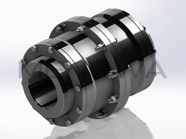
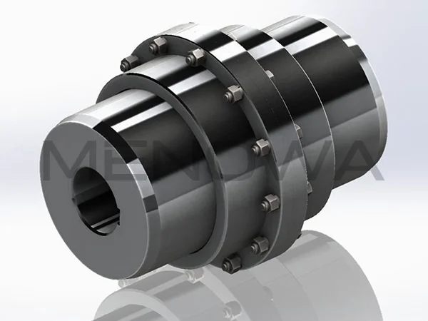
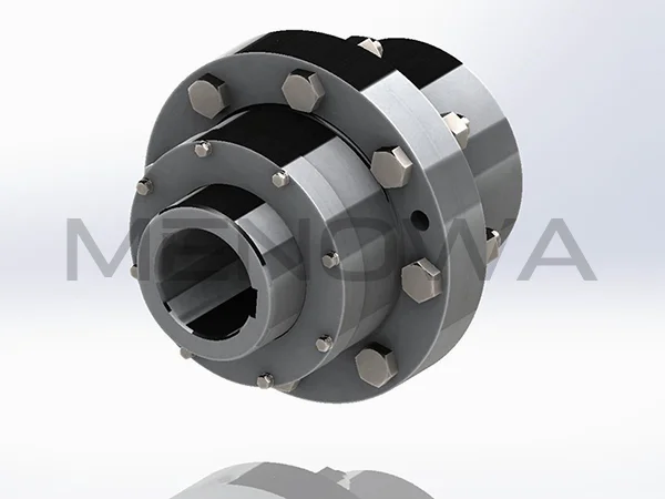
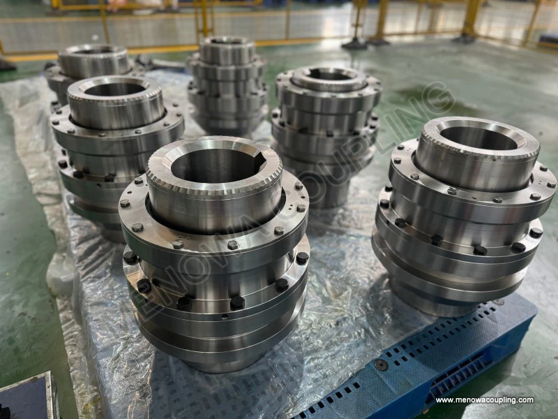
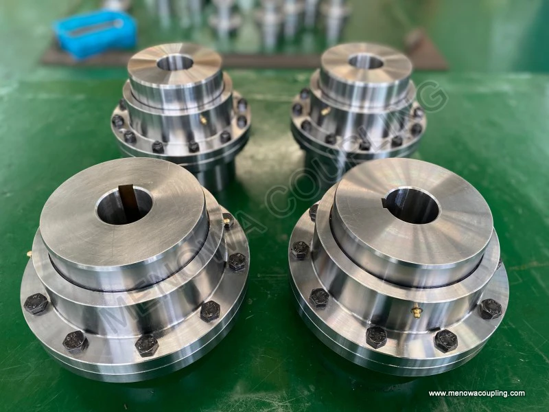
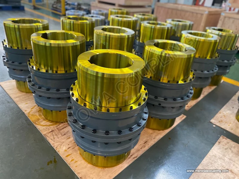
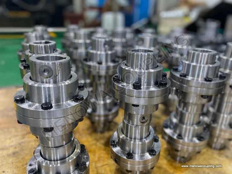
Curved tooth coupling, also widely known as crowned gear coupling, remains one of the most widely adopted positive-locking flexible transmission components across global heavy-duty industrial markets, thanks to its outstanding torque capacity, multi-directional misalignment compensation and stable torsional rigidity under continuous cyclic loads. Unlike straight-tooth gear couplings that suffer from concentrated edge contact once shaft offset occurs, the spherical involute tooth profile of curved tooth couplings ensures full surface contact between internal and external gear teeth even when shafts deviate from the ideal coaxial line, which effectively lowers contact stress, reduces friction heat and greatly extends the overall service life of meshing components. In international mechanical transmission projects covering mining, metallurgy, cement production, marine power systems and bulk material conveying lines, this type of coupling occupies a dominant position among rigid-flexible transmission parts, yet many early equipment failures in cross-border industrial projects are traced back to improper daily maintenance and incorrect model selection rather than manufacturing defects of the coupling itself. Understanding systematic maintenance procedures together with scientific selection criteria can drastically cut unplanned downtime, lower component replacement frequency and improve long-term operational stability for global end users operating continuous production equipment under harsh working conditions. Before diving into maintenance routines, it is necessary to clarify the basic working mechanism that directly affects wear patterns and maintenance cycles. The whole assembly consists of two gear hubs with curved external teeth and one outer sleeve machined with internal teeth. Torque transfers from the driving shaft to the external gear hub, then through full meshing contact between curved teeth and inner sleeve teeth, and finally delivers power to the driven shaft hub. The crown modification on external teeth allows angular, radial and axial displacement simultaneously without generating sharp local pressure. Angular misalignment can normally reach up to 1.5 degrees for standard sizes, while radial offset is restricted by the tooth clearance and assembly structure. When misalignment exceeds the designed limit, sliding friction between tooth surfaces turns into severe abrasive wear, which becomes the primary cause of premature tooth pitting, tooth breakage and sleeve cracking. The tooth contact condition directly decides maintenance intervals, which makes regular inspection and lubrication the core of the whole maintenance management system for curved tooth couplings used worldwide.
The entire maintenance system can be divided into pre-operation preparation, routine periodic inspection, intermediate overhaul and troubleshooting for abnormal running conditions, all of which have been summarized and standardized in international heavy machinery operation specifications. Lubrication management ranks first among all maintenance items, as more than seventy percent of curved tooth coupling premature failures in global field applications stem from insufficient lubrication, contaminated grease or inappropriate lubricant grade selection. Metal-on-metal meshing of alloy steel gear teeth requires a stable oil film to separate contact surfaces and dissipate friction heat generated during high-torque transmission. For enclosed coupling structures running under moderate temperature and steady load, lithium-based extreme pressure grease is widely used in most general engineering equipment across Europe, Southeast Asia and North America. For high-speed rotating units and high-temperature working environments such as rotary kilns and metallurgical rolling equipment, high-temperature complex grease or liquid gear oil with high viscosity index is preferred to prevent oil film rupture under thermal load. The filling volume must follow structural limits: overfilling will cause excessive churning loss and continuous temperature rise inside the housing, while insufficient filling leaves partial tooth surfaces without protective oil film. For standard sleeve-type curved tooth couplings, the cavity should only be filled to fifty to sixty percent of the total internal space, leaving enough room for thermal expansion of lubricant and heat convection. Lubrication cycles differ drastically based on duty cycles and ambient dust levels. For indoor continuously running equipment with low dust concentration, re-greasing can be arranged every three to six months. For outdoor mining machinery, port bulk conveyors and sand processing equipment exposed to heavy dust, moisture and variable impact loads, the cycle needs to be shortened to four to eight weeks. When replenishing lubricant, old degraded grease mixed with metal powder and dust must be completely drained instead of simply injecting new grease on top of residual waste material. During long-term shutdown such as seasonal production suspension for overseas project sites, anti-rust grease should be coated evenly on all meshing tooth surfaces to avoid atmospheric corrosion and rust bonding between internal and external teeth, which will lead to tooth surface peeling when restarting the equipment after idle periods.
Visual and dimensional inspection forms the second major part of daily maintenance. Every scheduled shutdown should include disassembly of the coupling guard and visual check of gear tooth condition after cutting off power and implementing lockout safety procedures. Inspect each curved tooth surface uniformly to identify early signs including fine fatigue pitting, small spalling spots, linear abrasive scratches and micro-cracks along the tooth root. Minor pitting covering less than five percent of the total tooth contact area can be monitored continuously with shortened inspection intervals, but expanding pitting and obvious tooth root cracks mean the gear hub must be replaced immediately to avoid sudden fracture during peak torque output. Looseness of connecting bolts is another frequent problem in vibrating transmission systems. All fastening bolts connecting the sleeve and hubs should be checked with torque wrenches following cross tightening sequences to maintain even clamping force. Uneven bolt tension will create additional eccentric load on gear teeth and accelerate local wear. Besides component condition, shaft alignment needs periodic rechecking with dial indicators or laser alignment tools. Even if installation alignment meets tolerance requirements initially, thermal expansion of long transmission shafts, foundation settlement and long-term equipment vibration will gradually increase misalignment beyond the coupling’s allowable range. Every six months, radial runout and angular deviation between driving and driven shafts should be measured and adjusted back within designed limits. Many overseas plant operators ignore alignment re-calibration after equipment overhaul, resulting in continuous overload on curved teeth and shortened service life to less than one-third of the theoretical design value. Axial floating clearance also requires regular measurement. Excessive axial play will cause repeated impact between tooth end faces during frequent start-stop cycles, while too small clearance locks up the floating compensation function and eliminates the flexible performance of the curved tooth profile. Corrosion inspection cannot be overlooked for couplings installed in coastal chemical plants, offshore platform power equipment and humid tropical industrial zones. Salt fog and chemical vapor will erode unprotected tooth surfaces and hub outer circles, so surface anti-corrosion coating integrity must be checked, and corroded areas need cleaning and re-coating before rust spreads to the meshing zone.
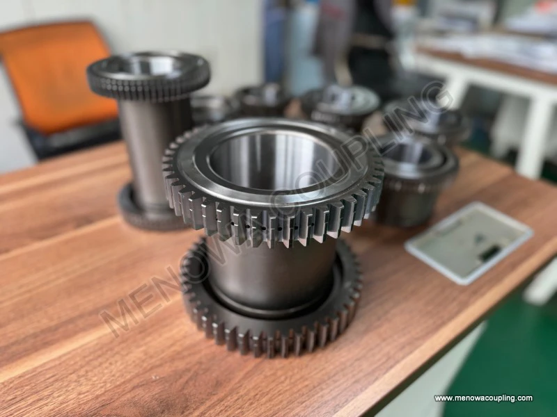
Intermediate overhaul should be arranged after twelve to eighteen months of continuous running or after thousands of start-stop cycles. The whole coupling assembly needs full disassembly for deep cleaning. Use solvent to wash away all residual deteriorated lubricant and metal wear debris trapped inside tooth gaps and housing cavities. After cleaning, inspect tooth profile deformation, tooth thickness reduction and keyway wear on gear hubs. Measure tooth thickness with gear calipers; when tooth thickness loss exceeds eight percent of the original dimension, the hub should be retired, as reduced tooth thickness lowers bending strength greatly under peak torque. Keyway clearance must be controlled within design limits. If keyway becomes widened due to repeated torque impact, it will produce circumferential backlash and periodic shock load on curved teeth. During reassembly, ensure internal and external curved teeth engage completely without one-sided contact. Mark the relative assembly position of the two hubs to maintain consistent meshing contact area after reinstallation. Do not force the sleeve into position with sledgehammer strikes, which will deform tooth profiles and create permanent local contact pressure points. After reassembly, test run the equipment under no-load condition first, monitoring running noise, vibration amplitude and surface temperature of the coupling housing. Sharp knocking noise indicates partial tooth engagement or foreign particles stuck between meshing surfaces; continuous temperature rise above normal operating temperature points to overfilling of lubricant or persistent shaft misalignment that needs readjustment immediately before putting the unit back into full-load production. For nylon-sleeve curved tooth couplings widely used in light and medium-duty hydraulic drive systems, maintenance focuses on sleeve aging, crack generation and tooth surface abrasion without frequent grease replacement. Once the polyamide sleeve develops radial cracks or obvious tooth deformation, the intermediate sleeve needs direct replacement without repair attempts, as repaired sleeves cannot maintain uniform meshing contact under alternating torque.
Abnormal condition troubleshooting complements regular maintenance and helps overseas maintenance teams reduce sudden breakdowns. Continuous high vibration during operation usually comes from three sources: severe tooth surface wear causing unbalanced mass, shaft misalignment exceeding compensation capacity, or loose fastening components. Abnormal high temperature mostly relates to failed lubrication, excessive meshing friction or tooth jamming caused by accumulated dirt. Irregular impact noise during startup and load variation often appears when tooth surfaces are severely spalled or key connections develop excessive backlash. In rainy and muddy working environments, water and silt penetrating into the coupling housing will wash away the oil film and form abrasive slurry between gear teeth, leading to rapid three-body abrasive wear. In such field conditions, the sealing gaskets on both ends of the sleeve need more frequent replacement to maintain enclosure tightness. Broken sealing elements are a common hidden fault ignored by maintenance personnel in mining and construction machinery operating in Africa, Australia and Latin America, and regular gasket inspection should be added to weekly maintenance checklists to block contaminant intrusion effectively.
Proper maintenance can only take effect on correctly selected coupling models; wrong specification remains a fundamental cause of frequent maintenance work and early failure, so mastering international standard selection methods becomes essential for end users and mechanical engineers purchasing curved tooth couplings for cross-border projects. The core selection formula focuses on calculating the calculated torque first, which is expressed as Tc = K × Tn. In this formula, Tc stands for the calculated design torque that the coupling must withstand, Tn is the nominal steady torque of the driving equipment, and K represents the service factor determined by load characteristics and duty cycles. The value range of K is widely recognized in global mechanical design practices: for uniform steady loads such as centrifugal fans and water pumps with fewer than five start-stop cycles per hour, K takes a value from 1.0 to 1.3; for equipment with moderate load fluctuation including belt conveyors and screw feeders, K is set between 1.5 and 1.8; for heavy impact loads such as crushers, rolling mills and hoisting machinery with frequent forward and reverse rotation, K needs to be raised to 2.0 up to 2.5. After obtaining the calculated torque Tc, the selected coupling’s allowable rated torque Ta must satisfy Ta ≥ Tc under the maximum continuous rotating speed. Speed restriction cannot be neglected either, as high centrifugal force will aggravate tooth meshing wear and lubricant deterioration. Every curved tooth coupling size has a limiting rotating speed based on structural balance and centrifugal stress, and the actual working speed must stay below this threshold value to avoid excessive vibration and heat generation.
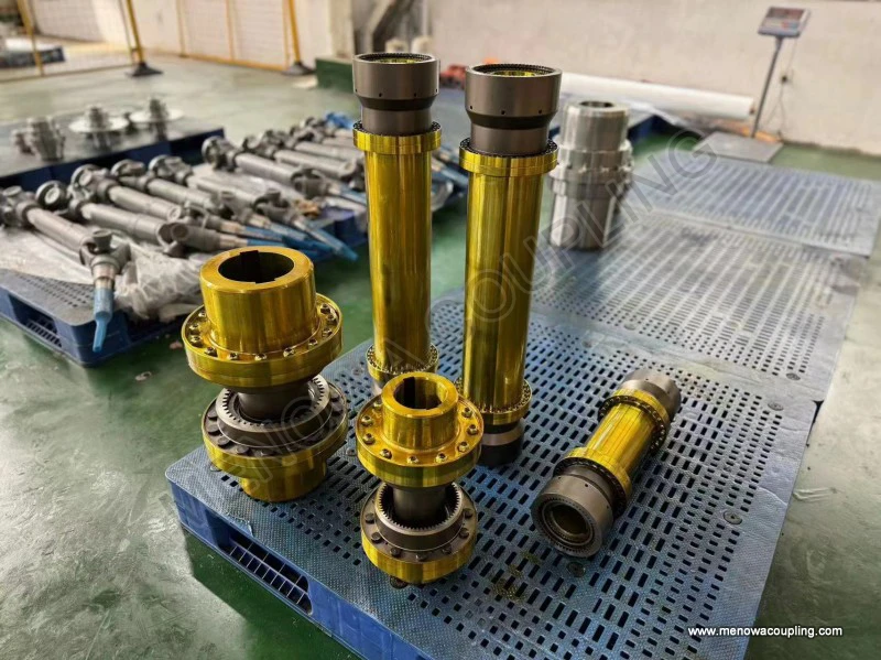
Besides torque and speed calculation, multiple structural and environmental factors must be considered during model confirmation. First comes misalignment compensation capacity. Measure the maximum possible angular, radial and axial displacement generated by shaft thermal expansion and foundation deformation. If the measured offset exceeds the compensation limit of standard single-section curved tooth couplings, intermediate-shaft type extended structures should be adopted to reduce additional bending stress on gear teeth. Second is installation space limitation. Measure the overall axial length and radial outer diameter available between driving and driven equipment. When the axial distance between two shafts is relatively long, couplings with intermediate sleeves become the preferred choice to avoid excessive cantilever load on gear hubs. Third is material selection matched with working conditions. For general moderate-load transmission in manufacturing workshops, medium carbon alloy steel with surface quenching treatment meets wear resistance requirements. For heavy-load continuous metallurgical and mining equipment, carburized alloy steel with deeper hardened layers is necessary to resist contact fatigue. In corrosive environments with acid, alkali or salt fog, low-carbon stainless steel material with proper surface passivation treatment can effectively slow down chemical corrosion on tooth surfaces and hubs. Fourth is the form of sealing structure. Open-type structures are only suitable for clean indoor low-speed transmission, while fully enclosed sealed designs with double rubber gaskets are mandatory for dusty outdoor sites and humid coastal industrial installations to block dust and moisture from entering the meshing zone and cutting down maintenance frequency significantly. The final step of selection is matching bore diameter and keyway dimensions strictly with the shaft size of driving motors and driven machines. Improper bore fit will produce gap or interference, causing hub creep on the shaft and accelerated keyway damage, which will bring repeated maintenance troubles even if torque capacity meets design requirements. Many cross-border procurement mistakes occur when engineers only compare torque parameters without checking bore tolerance and keyway form, leading to assembly difficulty and early failure after installation.
The global application scope of curved tooth couplings continues to expand year by year, covering almost all heavy-duty mechanical transmission fields that demand high torque transmission and reliable displacement compensation. In the metallurgical industry across Europe and Asia, rolling mill main transmission, furnace charging machinery and continuous casting line drive systems widely adopt heavy-duty curved tooth couplings to cope with thermal deformation-induced shaft offset and periodic impact load during metal rolling processes. The curved tooth profile keeps full tooth contact under angular deviation and maintains stable power transmission without frequent shutdown for alignment correction. In mining projects in Australia, South Africa and South America, crushing equipment, belt conveyors and mineral processing pumps operate under heavy dust, variable load and severe vibration conditions. The robust gear structure resists shock torque far better than elastomeric flexible couplings, and standardized maintenance procedures can keep the coupling running reliably for long production cycles. Cement production lines worldwide rely on curved tooth couplings installed on ball mills, rotary kilns and clinker conveyors; continuous non-stop operation for months requires low wear and long maintenance intervals, which this gear-type flexible coupling can perfectly deliver when lubrication and inspection are properly arranged. Marine propulsion systems and offshore platform generator sets also frequently use sealed curved tooth couplings to accommodate hull deformation and shaft vibration generated by ocean waves, with sealed housing preventing seawater from eroding internal gear teeth. General machinery including large fans, compressors, hydraulic pumps and bulk material handling equipment also chooses this coupling type for its high torsional rigidity and low backlash, which guarantees accurate rotational synchronization between driving and driven shafts without excessive elastic deformation. Only high-precision servo transmission systems with strict zero-backlash requirements will exclude curved tooth gear couplings, while all medium and heavy-duty industrial power transmission scenarios remain its core target market in international trade and mechanical engineering projects.
In the global industrial component market, the total ownership of curved tooth couplings keeps rising alongside the expansion of infrastructure, mineral development and continuous-process manufacturing. End users across different continents face distinct maintenance challenges due to climate and working environment differences. Operators in cold northern regions need to select low-temperature lubricant that will not solidify under sub-zero temperature to maintain a complete oil film during winter startup. Plant managers in tropical monsoon zones focus more on sealing integrity and anti-rust treatment to fight high humidity and rainwater infiltration. Mining contractors in desert areas prioritize dustproof structure and shorten grease replacement cycles to reduce abrasive wear caused by sand. No matter the regional operating conditions, the core logic remains consistent: stable lubrication, regular alignment correction, periodic tooth surface inspection and timely replacement of worn components. Systematic maintenance cannot only prolong coupling service life by two or three times compared with unmanaged operation, but also protect the connected motor, reducer and main machine from extra bending load brought by failed coupling components. Combining scientific calculation in model selection with standardized maintenance schedules helps global buyers avoid over-specification that raises procurement cost or under-specification that triggers frequent breakdowns. Recording inspection data, lubrication time, tooth wear status and overhaul content into equipment operation files will further optimize maintenance cycles and reduce unnecessary scheduled shutdowns. As international heavy industry pursues higher continuous operation rate and lower life-cycle cost, mastering the full set of maintenance practices for curved tooth couplings becomes a basic technical requirement for mechanical maintenance teams, project engineers and equipment procurement personnel all over the world. The curved tooth modification technology that distinguishes this coupling from ordinary straight gear products determines its superior anti-wear performance under misalignment, and only matching it with long-term strict maintenance management can fully release its design potential and create stable economic benefits for all industrial transmission systems running on global production sites.
Post Date: Jun 26, 2026
https://www.menowacoupling.com/china-coupling/maintenance-of-curved-tooth-coupling.html
Products
Tags
Supply
Related Articles
Coaxiality of Curved Tooth Coupling
In the global industrial transmission industry, curved tooth couplings have emerged as a core component of high-precision and high-torque shaft connection systems, widely adopted in heavy machinery, automated production lines, energy transmission equipment and cross-border industrial supporting fields. Coaxiality, as th…What is Gear Type Coupling
Gear type coupling is a fundamental flexible mechanical transmission component widely applied in modern industrial power transmission systems, serving as a critical connecting unit between two rotating shafts in mechanical equipment. Unlike rigid couplings that require precise shaft alignment and lack displacement compe…Gap Chart of Gear Type Coupling
Gear type couplings stand as one of the most widely used mechanical transmission components in industrial power systems, relied upon for their exceptional torque transmission capacity, high structural rigidity, and reliable adaptability to complex operating conditions. At the core of their stable operation lies the prec…Size Chart of Gear Type Coupling
A size chart of gear type coupling is an indispensable reference tool in industrial power transmission systems, serving as a bridge between the functional requirements of machinery and the technical specifications of the coupling itself. It systematically organizes key dimensional and performance parameters, allowing en…Barrel Gear Coupling Hubs
Barrel gear coupling hubs stand as indispensable foundational mechanical components within modern power transmission systems, serving as the key connecting medium that links driving shafts and driven shafts to achieve stable torque transfer, rotational motion synchronization, and effective compensation for various shaft…Components of Curved Tooth Coupling
In the global industrial transmission market, curved tooth couplings have emerged as one of the most indispensable core mechanical components for high-torque, high-speed, and misalignment-tolerant shaft connection systems. Widely adopted in heavy manufacturing, energy production, marine engineering, mining, and precisio…Gear Type Coupling Fabrication
Gear type coupling fabrication is a sophisticated and systematic manufacturing process focused on producing robust, flexible mechanical transmission components that connect rotating shafts to transmit torque while accommodating minor axial, radial, and angular misalignments. As a core component in mechanical transmissio…Maintenance of Gear Type Coupling
Gear type couplings serve as indispensable mechanical transmission components in industrial mechanical systems, widely applied in shaft connection scenarios of various rotating equipment to transmit torque, compensate for minor shaft displacement deviations, and buffer mechanical vibration generated during equipment ope…Working Principle of Gear Type Coupling
A gear type coupling is a mechanical device specifically designed to connect two rotating shafts, enabling the efficient transmission of torque and rotational motion while accommodating a certain degree of misalignment between the shafts. Unlike rigid couplings that require precise alignment to function properly, gear t…Barrel Gear Coupling Sleeves
Barrel gear coupling sleeves stand as essential structural and functional components within modern mechanical power transmission systems, serving as the central connecting medium that bridges driving and driven shafts across a vast range of industrial machinery and rotating equipment. In every mechanical setup that reli…
 WeChat
 WhatsApp