Size Chart of Grid Spring Coupling
A size chart of grid spring coupling is an indispensable reference tool in industrial transmission systems, serving as a bridge between the coupling’s design parameters and its practical application. It systematically organizes key dimensional data, enabling engineers, technicians, and procurement personnel to quickly select the appropriate coupling model that matches the operational requirements of mechanical equipment. Unlike simple parameter lists, a well-designed size chart integrates dimensional specifications with functional characteristics, providing comprehensive guidance for installation, maintenance, and performance optimization. To fully leverage the value of a grid spring coupling size chart, it is essential to understand its composition, the significance of each dimensional parameter, and how to apply it effectively in different industrial scenarios.

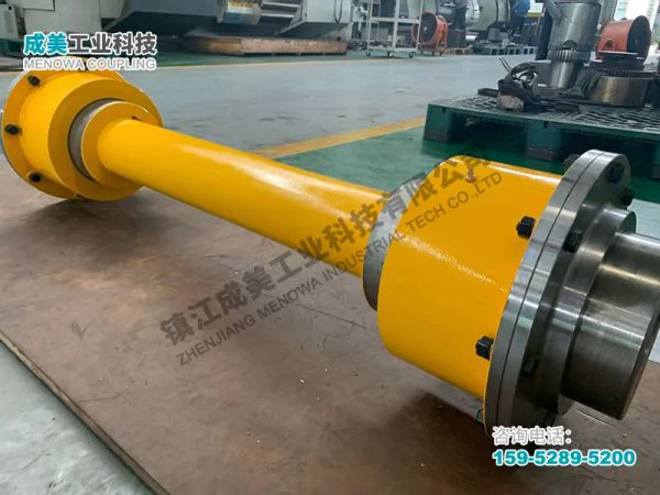
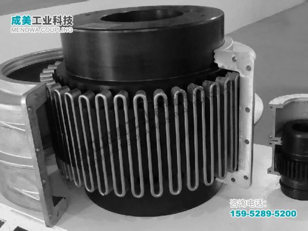
Grid spring couplings are widely used in various industrial fields due to their excellent shock absorption, vibration damping, and misalignment compensation capabilities. They play a critical role in connecting driving shafts and driven shafts, transmitting torque stably while protecting equipment from damage caused by sudden load changes or installation deviations. The size chart of such couplings is not merely a collection of numbers; it reflects the design logic of the coupling, the balance between structural strength and functional flexibility, and the adaptation to different working conditions. Every dimension recorded in the chart, from the outer diameter of the coupling to the size of the shaft hole, from the thickness of the grid spring to the length of the coupling body, is closely related to the coupling’s torque-bearing capacity, rotational speed limit, and service life. Therefore, mastering the content and application methods of the size chart is crucial for ensuring the safe and efficient operation of transmission systems.
The core content of a grid spring coupling size chart typically includes basic dimensional parameters, torque and speed specifications, and installation-related dimensions. Basic dimensional parameters form the foundation of the chart, covering the outer diameter (OD) of the coupling body, the inner diameter (ID) of the shaft hole, the length of the coupling, the thickness of the grid spring, and the number of teeth or slots on the coupling hubs. The outer diameter of the coupling directly affects its installation space and torque-bearing capacity; a larger outer diameter usually indicates a higher torque capacity, but it also requires more installation space. The inner diameter of the shaft hole must match the diameter of the driving and driven shafts to ensure a tight connection and stable torque transmission. If the shaft hole is too large, it may cause looseness during operation, leading to vibration and noise; if it is too small, it will be difficult to install and may even damage the shaft or the coupling.
The length of the coupling is another key parameter that influences both installation and performance. A longer coupling can provide better misalignment compensation, especially for axial misalignment, but it may reduce the overall rigidity of the transmission system. On the contrary, a shorter coupling has higher rigidity but limited misalignment compensation capacity. The thickness and material of the grid spring are closely related to the coupling’s shock absorption and fatigue resistance. Thicker grid springs can bear larger torques and have better impact resistance, while thinner springs offer more flexibility and better vibration damping effects. The number of teeth or slots on the coupling hubs affects the contact area between the grid spring and the hubs, thereby influencing the torque transmission efficiency and the uniformity of force distribution. More teeth or slots can distribute the torque more evenly, reducing local wear and extending the service life of the coupling.
In addition to basic dimensional parameters, the size chart also includes torque and speed specifications, which are critical for selecting the right coupling model. The rated torque of the coupling is the maximum torque it can transmit stably under normal operating conditions, and it must be greater than the actual torque required by the equipment. If the rated torque of the selected coupling is less than the actual torque, the grid spring may be overloaded, leading to deformation or breakage; if the rated torque is excessively larger than the actual torque, it will result in unnecessary waste of materials and space. The maximum allowable rotational speed of the coupling is determined by its structural strength and dynamic balance performance. Exceeding the maximum rotational speed may cause the coupling to vibrate violently, damage the bearings, or even lead to catastrophic failures. Therefore, when referring to the size chart, it is necessary to accurately calculate the actual torque and rotational speed of the equipment and select a coupling that meets or exceeds these requirements.
Installation-related dimensions in the size chart include the distance between the mounting flanges, the position of the bolt holes, the diameter of the bolts, and the allowable misalignment values. These dimensions ensure that the coupling can be correctly installed on the equipment and that the installation process is smooth and efficient. The distance between the mounting flanges must match the distance between the driving and driven shafts, and the position and diameter of the bolt holes must be consistent with the equipment’s mounting interface to ensure a secure connection. The allowable misalignment values, including radial, axial, and angular misalignment, indicate the maximum deviation that the coupling can compensate for during operation. Understanding these values is essential for proper installation and adjustment, as excessive misalignment can increase the load on the coupling and the bearings, reducing the service life of the entire transmission system.
To effectively use a grid spring coupling size chart, it is necessary to follow a systematic selection process. First, it is essential to collect detailed information about the equipment, including the rated power, rotational speed, torque, shaft diameter, installation space, and operating environment. This information provides the basis for selecting the appropriate coupling model. Next, based on the collected data, the actual torque and rotational speed of the equipment should be calculated. The actual torque is usually the rated torque multiplied by a load factor, which takes into account the impact of load fluctuations and starting conditions. The load factor varies depending on the type of equipment; for example, equipment with frequent starting and heavy load fluctuations, such as crushers and pumps, requires a higher load factor.
Once the actual torque and rotational speed are determined, the size chart can be used to select a coupling model with a rated torque and maximum rotational speed that meet or exceed the calculated values. At the same time, the basic dimensional parameters of the coupling, such as the outer diameter, shaft hole inner diameter, and coupling length, must be checked to ensure they match the equipment’s installation requirements. For example, if the installation space is limited, a coupling with a smaller outer diameter and shorter length should be selected, provided that it can meet the torque and speed requirements. If the shaft diameter of the equipment is non-standard, it may be necessary to customize the coupling according to the size chart, adjusting the shaft hole inner diameter to ensure a perfect fit.
It is also important to consider the operating environment when using the size chart. Different operating environments have different requirements for the coupling’s material and structural design. For example, in high-temperature environments, such as in the metallurgical industry, the coupling should be made of high-temperature resistant materials to prevent deformation or damage caused by high temperatures. In humid or corrosive environments, such as in the chemical industry, the coupling should be treated with anti-corrosion coatings to improve its durability. The size chart may include information about the material and corrosion resistance of the coupling, which can be used as a reference when selecting the appropriate model for specific environments.
Another key aspect of using the size chart is to understand the relationship between different dimensional parameters. For example, there is a certain correlation between the outer diameter of the coupling and its rated torque; generally, as the outer diameter increases, the rated torque also increases. However, this relationship is not linear, as it is also affected by the material, structural design, and manufacturing process of the coupling. Similarly, the length of the coupling and its misalignment compensation capacity are positively correlated, but excessive length may affect the stability of the transmission system. Therefore, when selecting a coupling, it is necessary to balance various dimensional parameters to achieve the optimal performance.
In addition to selection, the size chart also provides important guidance for the installation and maintenance of grid spring couplings. During installation, the dimensions of the coupling, such as the shaft hole inner diameter and the position of the bolt holes, must be carefully checked to ensure they match the equipment. The allowable misalignment values in the size chart should be strictly followed to avoid excessive misalignment, which can cause premature wear of the grid spring and bearings. During maintenance, the size chart can be used to check the wear and deformation of the coupling components. For example, if the thickness of the grid spring is found to be less than the minimum value specified in the size chart, it should be replaced in a timely manner to prevent failure.
It is worth noting that the size chart of grid spring couplings may vary slightly depending on the design and manufacturing standards. Different manufacturers may have different dimensional specifications for couplings of the same model, but the core parameters, such as rated torque, maximum rotational speed, and basic dimensions, are generally consistent with industry standards. Therefore, when using the size chart, it is necessary to confirm the applicable standards and ensure that the selected coupling meets the relevant technical requirements. In addition, with the continuous development of industrial technology, the design and performance of grid spring couplings are constantly improving, and the size chart should be updated accordingly to reflect the latest product specifications.
Common misunderstandings in the use of grid spring coupling size charts should also be avoided. One common misunderstanding is that only the rated torque and rotational speed need to be considered when selecting a coupling, ignoring the influence of dimensional parameters such as outer diameter and length. This can lead to installation difficulties or insufficient performance of the coupling. Another misunderstanding is that the larger the coupling size, the better. In fact, an excessively large coupling not only increases the cost and installation space but also may reduce the flexibility of the transmission system and increase energy consumption. Therefore, it is necessary to select the coupling size reasonably based on the actual needs of the equipment.
In practical applications, the size chart of grid spring couplings is often used in conjunction with other technical documents, such as installation manuals and maintenance guides. These documents provide detailed information about the installation steps, maintenance methods, and troubleshooting measures of the coupling, which, together with the size chart, ensure the safe and stable operation of the coupling. For example, the installation manual may specify the torque required to tighten the bolts, which is related to the bolt diameter specified in the size chart. The maintenance guide may recommend the frequency of lubrication and inspection, which is related to the working conditions and dimensional parameters of the coupling.
The importance of the size chart becomes even more prominent in large-scale industrial projects, where multiple couplings are used in different parts of the transmission system. In such projects, the size chart can help standardize the selection and installation of couplings, ensuring the consistency and compatibility of the entire transmission system. It also facilitates the management and maintenance of the couplings, as technicians can quickly find the relevant dimensional parameters and performance specifications of each coupling by referring to the size chart.
In conclusion, the size chart of grid spring coupling is a vital tool in industrial transmission systems, providing comprehensive and accurate dimensional and performance information for the selection, installation, and maintenance of couplings. By understanding the composition and significance of the size chart, following the correct selection process, and considering the actual operating conditions and requirements of the equipment, engineers and technicians can select the most suitable grid spring coupling, ensuring the safe, efficient, and stable operation of the transmission system. As industrial technology continues to advance, the size chart will continue to be optimized and improved, playing an even more important role in the development of industrial production.
Post Date: May 13, 2026
https://www.menowacoupling.com/china-coupling/size-chart-of-grid-spring-coupling.html

Supply
Related Articles
Coaxiality of Grid Spring Coupling
Coaxiality is a critical geometric parameter that directly determines the performance, reliability, and service life of grid spring couplings, which are widely used in various industrial transmission systems to connect two rotating shafts and transmit torque while compensating for minor misalignments. In essence, coaxia…Grid Spring Coupling Supplier
In the complex and interconnected world of industrial machinery, the role of coupling components cannot be overstated. These critical parts serve as the bridge between rotating shafts, ensuring the smooth and efficient transmission of power while accommodating misalignments and reducing operational stress. Among the var…Elastic Coupling Supply
In the realm of industrial power transmission, elastic couplings serve as a critical bridge between rotating shafts, enabling the smooth transfer of torque while mitigating the negative effects of misalignment, vibration, and shock loads. The supply of elastic couplings is a dynamic and essential component of modern man…Structure of Grid Spring Coupling
The grid spring coupling is a crucial component in industrial power transmission systems, designed to connect two rotating shafts while accommodating misalignments, absorbing vibrations, and protecting machinery from shock loads. Its unique structure combines the rigidity needed for efficient torque transmission with th…Types of Elastic Coupling
Elastic couplings are essential mechanical components designed to connect two rotating shafts in machinery, enabling the efficient transmission of torque while accommodating minor misalignments, absorbing shocks, and dampening vibrations. Unlike rigid couplings, which require precise alignment and offer no flexibility, …Characteristics of Grid Spring Coupling
A grid spring coupling is a specialized mechanical component designed to transmit torque between two rotating shafts while accommodating various forms of misalignment and mitigating the effects of vibration and shock loads. Unlike rigid couplings that require precise alignment and offer no flexibility, grid spring coupl…Grid Spring Coupling Fabrication
Grid spring couplings are essential components in mechanical transmission systems, widely used in various industrial fields due to their unique combination of flexibility, torque transmission capacity, and durability. These couplings play a critical role in connecting two rotating shafts, compensating for misalignments,…Components of Grid Spring Coupling
A grid spring coupling is a sophisticated mechanical device designed to transmit torque between two rotating shafts while accommodating misalignments, absorbing vibrations, and cushioning shock loads. Its robust yet flexible structure makes it indispensable in a wide range of industrial applications, from heavy machiner…Material of Grid Spring Coupling
Grid spring couplings are essential components in mechanical transmission systems, designed to connect two shafts and transmit torque while compensating for axial, radial, and angular misalignments, absorbing vibrations, and reducing shock loads. The performance, reliability, and service life of a grid spring coupling a…Maintenance of Grid Spring Coupling
Grid spring couplings are widely used in various industrial transmission systems, serving as a critical connection between driving and driven shafts to transmit torque while compensating for axial, radial, and angular misalignments. Their unique structure, which relies on grid springs embedded in the tooth grooves of tw…
 WeChat
 WhatsApp