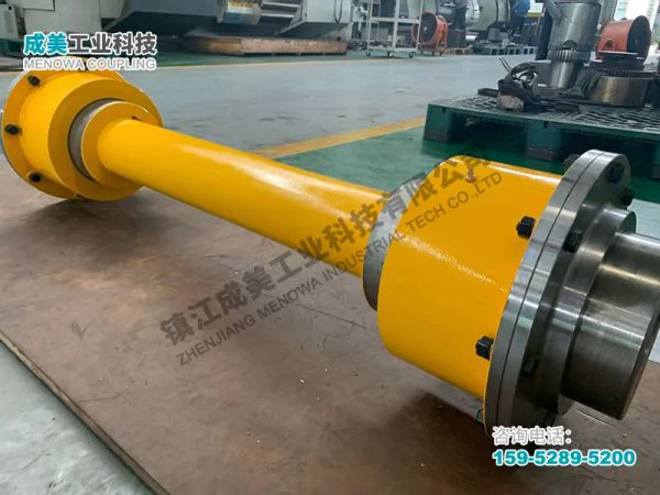
Structure of Grid Spring Coupling
The grid spring coupling is a crucial component in industrial power transmission systems, designed to connect two rotating shafts while accommodating misalignments, absorbing vibrations, and protecting machinery from shock loads. Its unique structure combines the rigidity needed for efficient torque transmission with the flexibility required to handle dynamic operating conditions, making it widely used in various industries such as mining, metallurgy, construction, and general machinery. To fully understand the functionality and advantages of this coupling type, it is essential to delve into its detailed structure, including the core components, their design characteristics, material selections, and the synergistic effects that enable its reliable performance. Unlike rigid couplings that create a direct, inflexible connection between shafts, the grid spring coupling utilizes a combination of metallic components and elastic elements to achieve a balance between torque transfer efficiency and operational flexibility, ensuring smooth power transmission even in harsh working environments.

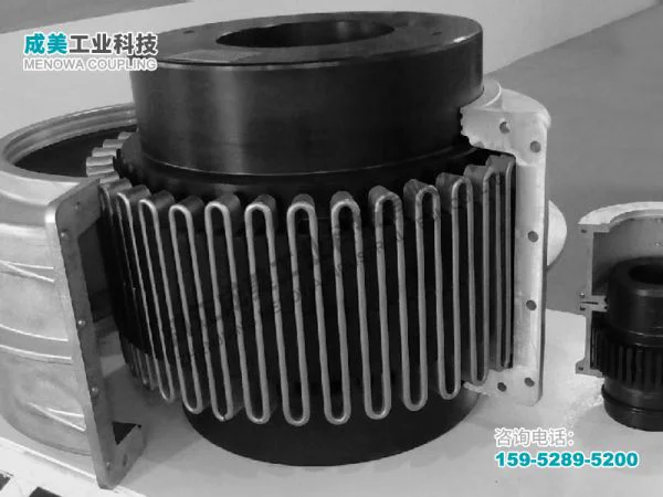
At the heart of the grid spring coupling lies the grid spring itself, which serves as the primary elastic element and torque-transmitting component. This spring is typically formed into a continuous, serpentine (or grid-like) shape, distinct from traditional helical or cylindrical springs, and is specifically designed to fit within the mating grooves of the coupling’s other components. The serpentine structure of the grid spring is not arbitrary; it is engineered to provide controlled elasticity, allowing for axial, radial, and angular misalignment compensation while maintaining high torque-carrying capacity. The shape of the grid spring features a series of alternating curves that create multiple contact points with the coupling’s hubs, distributing the transmitted torque evenly across the entire surface area and reducing stress concentrations. This design also enables the spring to absorb and dissipate shock energy during startup, shutdown, or sudden load changes, preventing damage to the connected equipment such as motors, reducers, and work machines.
The grid spring’s dimensions and geometric parameters are carefully calculated based on the intended application’s torque requirements and operating conditions. The thickness, width, and curvature of the spring coils are optimized to balance flexibility and strength—too much flexibility would result in insufficient torque transmission, while excessive rigidity would limit the coupling’s ability to compensate for misalignments and absorb vibrations. The spring is usually formed as a single continuous piece, though in some heavy-duty applications, multiple grid springs may be used in parallel to increase the overall torque capacity. The ends of the grid spring are often shaped to fit securely within the grooves of the hubs, ensuring that there is no slippage during operation and that the torque is transferred efficiently from the driving shaft to the driven shaft. Additionally, the serpentine shape allows the spring to undergo elastic deformation in multiple directions, making it highly adaptable to the dynamic misalignments that commonly occur in industrial machinery due to installation errors, thermal expansion, or structural deflection.
Complementing the grid spring are the two hubs, also known as half-couplings, which are the primary structural components that connect the coupling to the driving and driven shafts. Each hub is a cylindrical or flanged component with a central bore designed to fit precisely onto the shaft, secured by keys, set screws, or hydraulic clamping mechanisms to ensure a tight, slip-free connection. The outer surface of each hub features a series of circumferential grooves that are machined to match the curvature of the grid spring, creating a mating interface that allows the spring to fit securely within the hubs. The grooves are typically spaced evenly around the circumference of the hub, ensuring that the torque is distributed uniformly across the grid spring and preventing localized stress concentrations that could lead to premature failure. The design of the grooves is critical—their depth, width, and curvature must align perfectly with the grid spring to ensure maximum contact area and efficient torque transfer, while also providing enough clearance for the spring to deform elastically during operation.
The hubs are subjected to significant mechanical stress during operation, as they must transmit the full torque from the driving shaft to the grid spring and then to the driven shaft. As a result, the material selection for the hubs is carefully considered to ensure high strength, durability, and resistance to wear and fatigue. Common materials used for the hubs include high-quality carbon steel, alloy steel, or cast steel, which are heat-treated to enhance their mechanical properties. Heat treatment processes such as quenching and tempering are often applied to increase the hardness and tensile strength of the hubs, making them capable of withstanding the high torques and dynamic loads encountered in industrial applications. The surface of the hub grooves may also be subjected to additional treatments, such as grinding or polishing, to reduce friction between the hub and the grid spring, minimizing wear and extending the service life of both components.
Another essential component of the grid spring coupling is the outer cover, also referred to as the housing or guard, which encloses the grid spring and the hub grooves. The primary function of the outer cover is to protect the internal components from external contaminants such as dust, dirt, moisture, and debris, which can cause wear, corrosion, or premature failure of the grid spring and hubs. In addition to protection, the outer cover also serves to contain the lubricant that is used to reduce friction between the grid spring and the hubs, preventing lubricant leakage and ensuring that the moving components remain properly lubricated. The outer cover is typically a two-piece structure, consisting of two semicircular shells that are bolted together around the hubs, allowing for easy disassembly and maintenance. The cover is usually made from cast iron, steel, or aluminum alloy, depending on the application’s requirements for strength, weight, and corrosion resistance. Aluminum alloy covers are often used in applications where weight is a concern, while cast iron or steel covers are preferred for heavy-duty applications that require greater strength and durability.
Sealing components are integrated into the outer cover to further enhance its protective function. These seals are typically made from elastomeric materials such as nitrile rubber or silicone, which are resistant to lubricants and capable of forming a tight seal between the outer cover and the hubs. The seals prevent external contaminants from entering the coupling and also prevent lubricant from leaking out, ensuring that the internal components remain clean and properly lubricated. The design of the seals is tailored to the coupling’s operating conditions, including temperature, speed, and the type of lubricant used, to ensure optimal sealing performance over an extended service life. In some cases, labyrinth seals may be used in addition to elastomeric seals to provide an extra layer of protection against contaminants, particularly in harsh environments such as mining or construction sites where dust and debris are prevalent.
Lubrication is a critical aspect of the grid spring coupling’s structure and performance, as it reduces friction between the grid spring and the hubs, minimizes wear, and dissipates heat generated during operation. The type of lubricant used is carefully selected based on the coupling’s operating speed, temperature, and torque requirements. Common lubricants include lithium-based greases, which offer excellent lubrication properties, high temperature resistance, and good water resistance, making them suitable for most industrial applications. The lubricant is applied to the grid spring and the hub grooves during assembly, and periodic re-lubrication is required to maintain optimal performance. The outer cover is designed with a lubrication fitting or port that allows for easy re-lubrication without disassembling the coupling, reducing maintenance time and costs. Proper lubrication not only extends the service life of the coupling components but also ensures smooth operation, reduces vibration, and prevents premature failure due to friction-induced wear or overheating.
The assembly of the grid spring coupling involves several key steps to ensure that all components work together seamlessly. First, the hubs are mounted onto the driving and driven shafts, secured with the appropriate fasteners to ensure a tight fit. The grid spring is then carefully placed into the grooves of one of the hubs, ensuring that it fits securely and aligns properly with the grooves. The second hub is then positioned onto the other shaft and aligned with the first hub, allowing the grid spring to fit into the grooves of the second hub. The outer cover is then bolted together around the hubs, ensuring that the seals are properly seated to prevent lubricant leakage and contamination. Finally, lubricant is added through the lubrication port to fill the internal cavity, ensuring that all moving components are properly lubricated. The assembly process requires precision to ensure that the hubs are aligned correctly, the grid spring is properly seated, and the outer cover is securely fastened, as any misalignment or improper assembly can lead to reduced performance, increased wear, or premature failure.
The design of the grid spring coupling is also influenced by the need to accommodate different types of misalignments that can occur between the driving and driven shafts. These misalignments include axial misalignment (where the shafts are offset along their common axis), radial misalignment (where the shafts are offset perpendicular to their common axis), and angular misalignment (where the shafts are inclined relative to each other). The grid spring’s serpentine structure allows it to deform elastically to compensate for these misalignments, ensuring that the torque is transmitted smoothly without imposing excessive stress on the shafts or the connected equipment. The amount of misalignment that the coupling can accommodate depends on the design of the grid spring, the size of the coupling, and the material properties of the components. In general, grid spring couplings can accommodate axial misalignments of several millimeters, radial misalignments of up to a few tenths of a millimeter, and angular misalignments of up to one degree or more, making them highly versatile for a wide range of industrial applications.
Material selection for the grid spring is another critical factor that affects the coupling’s performance and service life. The grid spring must possess high elasticity, fatigue resistance, and tensile strength to withstand repeated elastic deformation during operation without permanent damage. Common materials used for the grid spring include high-quality spring steels such as 60Si2Mn, 50CrVA, and SAE 9254, which are known for their excellent mechanical properties and resistance to fatigue. These materials are typically cold-wound into the serpentine shape and then heat-treated to enhance their elastic properties and durability. Heat treatment processes such as quenching and tempering are used to achieve a balance between hardness and toughness, ensuring that the spring can withstand high torques and repeated deformation while remaining flexible. In some cases, the grid spring may also be subjected to shot peening, a surface treatment process that increases the surface hardness, reduces surface defects, and improves fatigue resistance by creating a compressive stress layer on the surface of the spring.
The performance of the grid spring coupling is also influenced by the design of the hub grooves. The grooves are typically machined with a curved profile that matches the curvature of the grid spring, ensuring maximum contact area between the spring and the hubs. This large contact area distributes the torque evenly, reducing stress concentrations and minimizing wear. The depth of the grooves is designed to allow the grid spring to deform elastically without bottoming out, ensuring that the spring can absorb vibrations and compensate for misalignments effectively. The width of the grooves is slightly larger than the width of the grid spring to allow for thermal expansion and to ensure that the spring can move freely within the grooves during operation. Additionally, the edges of the grooves are often rounded to prevent sharp edges from damaging the grid spring during assembly or operation.
In addition to the core components, the grid spring coupling may also include additional features to enhance its performance and usability. For example, some couplings are equipped with torque limiters, which are designed to protect the coupling and the connected equipment from excessive torque. These torque limiters work by allowing the grid spring to slip or deform plastically when the torque exceeds a predetermined limit, preventing damage to the shafts, motors, or other components. Other couplings may include balancing features, such as counterweights, to ensure that the coupling rotates smoothly at high speeds, reducing vibration and extending the service life of the bearing and other components. These additional features are tailored to the specific requirements of the application, ensuring that the coupling meets the performance and safety needs of the industrial system.
The operational characteristics of the grid spring coupling are directly related to its structure. The combination of the grid spring and the hubs creates a flexible connection that allows for torque transmission while absorbing vibrations and compensating for misalignments. The serpentine grid spring acts as a shock absorber, absorbing the impact energy generated during startup, shutdown, or sudden load changes, and converting it into elastic potential energy that is gradually released. This reduces the stress on the connected equipment, extending its service life and improving overall system reliability. The lubricated interface between the grid spring and the hubs minimizes friction, reducing energy loss and heat generation, which further enhances the coupling’s efficiency and durability.
Maintenance is an important aspect of ensuring the long-term performance of the grid spring coupling, and its structure is designed to facilitate easy maintenance. The two-piece outer cover allows for quick access to the internal components, making it easy to inspect the grid spring, hubs, and seals for wear, damage, or contamination. The lubrication port allows for easy re-lubrication without disassembling the entire coupling, reducing maintenance time and costs. Regular maintenance activities include inspecting the coupling for signs of wear or damage, checking the lubricant level and condition, and replacing worn or damaged components such as the grid spring, seals, or hubs. Proper maintenance ensures that the coupling operates at peak performance, reduces the risk of unexpected failure, and extends its service life.
The versatility of the grid spring coupling is due in large part to its modular structure, which allows for customization to meet the specific requirements of different applications. The size of the coupling can be adjusted based on the torque and speed requirements, with larger couplings designed for heavy-duty applications and smaller couplings for light to medium-duty applications. The material of the components can also be customized to suit the operating environment—for example, corrosion-resistant materials can be used in marine or chemical applications, while high-temperature materials can be used in applications where the coupling is exposed to elevated temperatures. Additionally, the design of the grid spring and hubs can be modified to accommodate specific misalignment requirements, torque capacities, or operating speeds, making the grid spring coupling suitable for a wide range of industrial applications.
In summary, the structure of the grid spring coupling is a carefully engineered combination of core components that work together to provide efficient torque transmission, vibration absorption, and misalignment compensation. The grid spring, as the central elastic element, is designed to balance flexibility and strength, while the hubs provide a secure connection to the shafts and distribute torque evenly. The outer cover and seals protect the internal components from contamination and lubricant leakage, ensuring reliable operation in harsh environments. Material selection, heat treatment, and precision machining are critical to the performance and durability of the coupling, with each component designed to withstand the mechanical stresses and operating conditions of industrial applications. The modular design of the grid spring coupling allows for customization, making it a versatile and reliable choice for power transmission systems across a wide range of industries. By understanding the detailed structure and function of each component, it is possible to appreciate the unique advantages of the grid spring coupling and its role in ensuring the smooth, efficient, and reliable operation of industrial machinery.
Post Date: May 6, 2026
https://www.menowacoupling.com/china-coupling/structure-of-grid-spring-coupling.html

Supply
Related Articles
Dimensions of Grid Spring Coupling
The grid spring coupling is a critical component in mechanical transmission systems, widely utilized across various industrial sectors due to its exceptional ability to accommodate misalignments, dampen vibrations, and transmit torque efficiently. While its functional advantages are well-recognized, the dimensions of a …Grid Spring Coupling Supplier
In the complex and interconnected world of industrial machinery, the role of coupling components cannot be overstated. These critical parts serve as the bridge between rotating shafts, ensuring the smooth and efficient transmission of power while accommodating misalignments and reducing operational stress. Among the var…Characteristics of Grid Spring Coupling
A grid spring coupling is a specialized mechanical component designed to transmit torque between two rotating shafts while accommodating various forms of misalignment and mitigating the effects of vibration and shock loads. Unlike rigid couplings that require precise alignment and offer no flexibility, grid spring coupl…Components of Grid Spring Coupling
A grid spring coupling is a sophisticated mechanical device designed to transmit torque between two rotating shafts while accommodating misalignments, absorbing vibrations, and cushioning shock loads. Its robust yet flexible structure makes it indispensable in a wide range of industrial applications, from heavy machiner…Diagram of Grid Spring Coupling
A grid spring coupling is a versatile mechanical device designed to transmit torque between two rotating shafts while accommodating misalignments, absorbing shock loads, and reducing vibration in various industrial applications. Its unique structural design, which combines rigidity with flexibility, makes it an indispen…Grid Spring Coupling Manufacture
Grid spring couplings are essential mechanical components widely used in industrial power transmission systems, serving as the critical connection between driving and driven shafts to transmit torque while accommodating misalignments and absorbing shocks. The manufacture of grid spring couplings requires precise enginee…Gap Chart of Grid Spring Coupling
The gap chart of grid spring coupling is an indispensable technical document in the field of mechanical transmission, serving as a core guide for the installation, operation, maintenance, and fault diagnosis of grid spring couplings. Grid spring couplings, as a type of metallic flexible coupling widely used in medium to…
 WeChat
 WhatsApp