Parts of Flexible Diaphragm Coupling
A flexible diaphragm coupling stands as a vital mechanical transmission component widely adopted in high-precision and high-speed industrial transmission systems, serving the core purpose of connecting driving and driven shafts to achieve stable torque transmission while compensating for diverse shaft misalignments generated during mechanical operation. Unlike traditional rigid couplings and elastic couplings with rubber or plastic buffer components, this type of coupling relies on the elastic deformation of metal thin-plate structures to realize flexibility, featuring zero clearance transmission, long service life, and maintenance-free operation under conventional working conditions. The superior comprehensive performance of flexible diaphragm couplings stems from the precise coordination and scientific structural design of each internal component. Every part undertakes independent functional responsibilities while forming an integrated operating system, jointly guaranteeing the efficiency, stability, and durability of the entire transmission mechanism. An in-depth understanding of the structural characteristics and working functions of each component is essential for grasping the operating logic of diaphragm couplings and optimizing their application in different industrial scenarios.
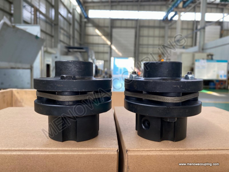
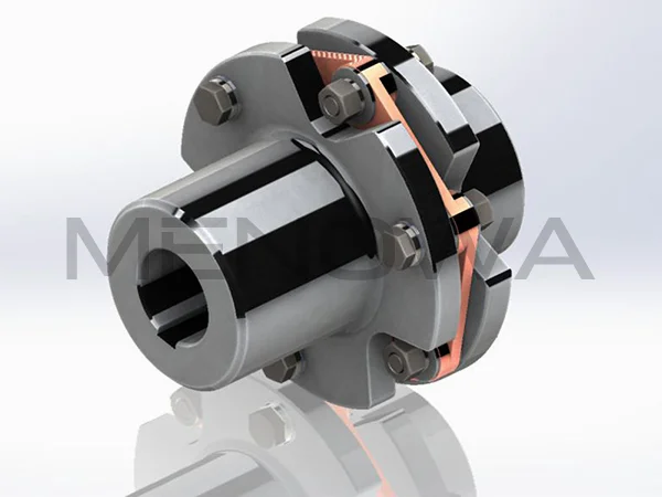
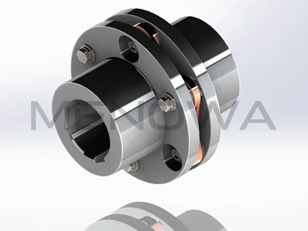
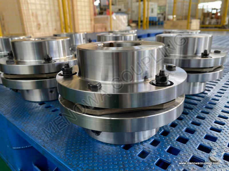
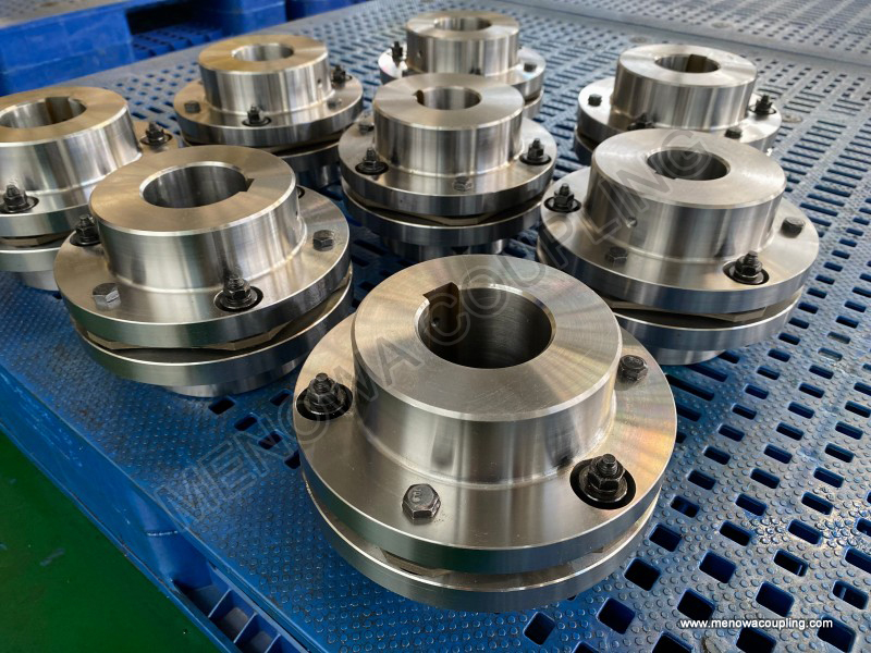
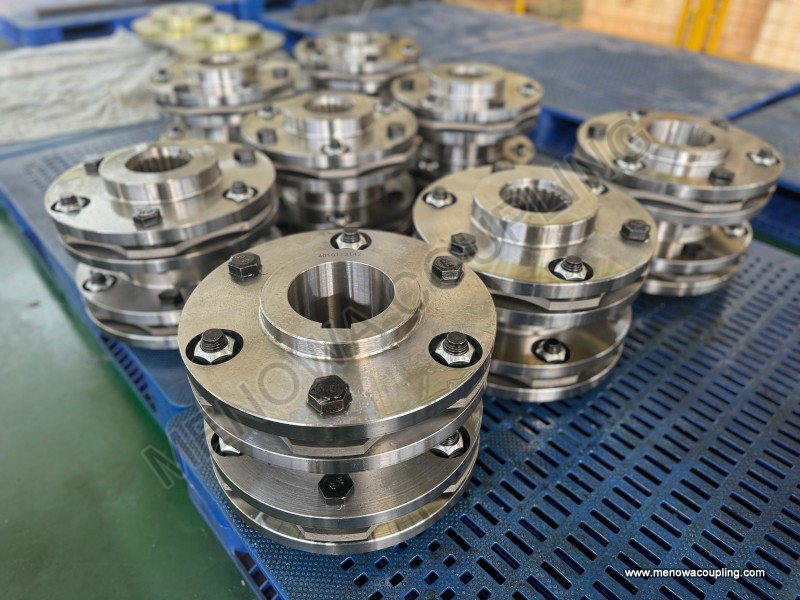
The hub, also known as the half coupling, constitutes the basic connecting base of the flexible diaphragm coupling and exists in pairs in a complete coupling set, respectively fixed on the driving shaft and driven shaft of mechanical equipment. As the core force-bearing and connecting component, the hub needs to bear cyclic torque, axial tension and compression, and slight radial impact during long-term continuous operation, so its structural design and material selection follow strict mechanical performance standards. Most hubs adopt high-strength alloy steel integral forging molding technology, which effectively eliminates internal structural defects such as pores and cracks, and significantly improves overall rigidity, wear resistance, and fatigue resistance compared with cast structures. The inner wall of the hub is designed with a matching connecting structure that fits the equipment shaft. The most common structural form is the keyway connection structure. The standard keyway can realize tight assembly and torque transmission between the hub and the shaft, avoiding relative rotation and slipping during high-speed operation. In addition to keyway structures, some hubs adopt interference fit or spline connection designs according to working condition requirements, which can achieve higher connection precision and uniform torque transmission, suitable for ultra-high-speed and high-precision transmission scenarios.
The outer side of the hub is distributed with evenly arranged mounting holes, which are used for penetrating fastening bolts to realize fixed connection with the diaphragm group. The hole position distribution strictly follows the symmetrical mechanical design principle, ensuring uniform stress on each connecting point during torque transmission and avoiding local stress concentration caused by uneven force distribution. The end face of the hub that fits with the diaphragm is processed with high-precision flatness and roughness to ensure close contact with the diaphragm surface, eliminate assembly gaps, and prevent micro-vibration and torque loss caused by poor fitting during operation. In actual operation, the hub acts as the torque input and output terminal of the coupling. The torque generated by the driving equipment is first transmitted to the driving side hub through the shaft, and then the hub transmits the torque to the diaphragm group through the fastening structure. After the flexible compensation of the diaphragm group, the torque is transmitted to the driven side hub, and finally stably output to the driven equipment shaft. This structural layout ensures that the entire torque transmission process is continuous and efficient, and the high rigidity of the hub also effectively maintains the overall structural stability of the coupling, avoiding structural deformation and displacement under high-load working conditions.
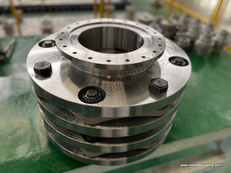
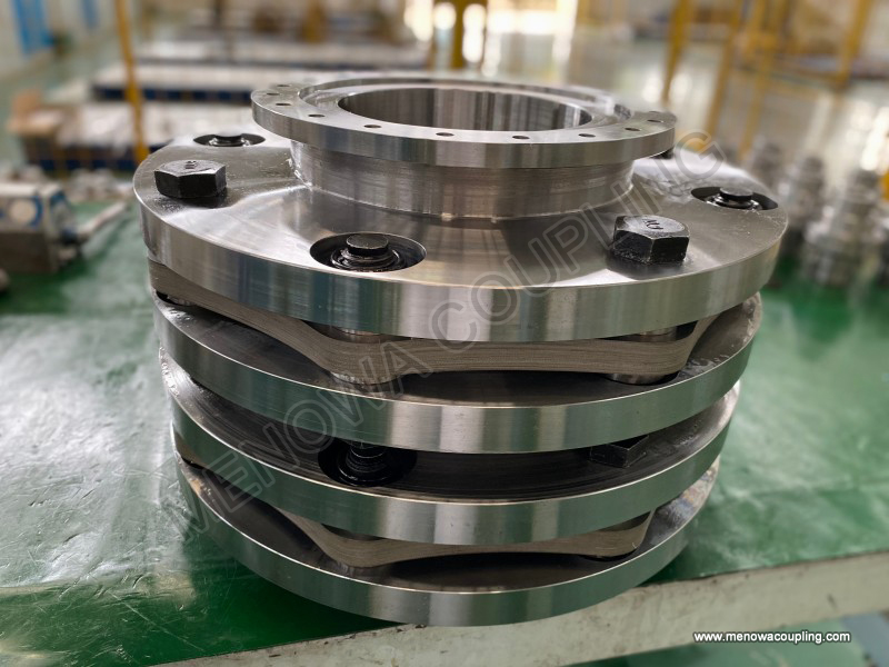
The diaphragm group is the core flexible functional component of the flexible diaphragm coupling and the key structure that distinguishes it from other types of rigid couplings. It is mainly composed of multiple stacked ultra-thin high-strength metal thin plates, and a small number of lightweight models adopt a single-layer diaphragm structure. The metal diaphragm materials are mostly high-quality stainless steel or alloy steel with excellent elastic fatigue resistance, which can undergo repeated elastic deformation under long-term cyclic load without plastic deformation or fatigue fracture. Different from ordinary elastic components, the diaphragm group realizes flexible compensation through micro elastic bending and stretching deformation, without friction, sliding or wear during operation, which fundamentally avoids the performance attenuation and failure problems caused by component wear. Each diaphragm is designed with a special contour structure, mostly circular or special-shaped corrugated structures. This structural design can effectively improve the deformation flexibility of the diaphragm, enabling it to adapt to axial displacement, radial offset and angular deflection between the two connected shafts.
In the working process, when the driving shaft and driven shaft produce misalignment due to equipment operation vibration, installation errors or thermal expansion and contraction, the diaphragm group will produce corresponding elastic deformation to absorb and compensate for these displacement deviations. For axial misalignment, the diaphragm realizes axial stretching and contraction through elastic deformation to adapt to the axial floating of the shaft; for radial offset, the diaphragm produces bending deformation in the radial direction to offset the parallel displacement between the shafts; for angular deflection, the multi-point stress of the diaphragm is unevenly distributed, and the elastic difference of different parts realizes angle compensation. The multi-layer stacked structure of the diaphragm group has obvious performance advantages. Compared with a single-layer thick diaphragm, the superposition of multiple thin diaphragms can obtain greater overall flexibility and compensation range on the premise of ensuring structural strength, and can also disperse the stress generated by deformation, reduce the stress value of a single diaphragm, and greatly extend the fatigue service life of the component. Meanwhile, the gaps between the stacked diaphragms can form a tiny heat dissipation space, which can timely discharge the heat generated by micro deformation during high-speed operation, avoid local high-temperature aging of metal materials, and maintain stable mechanical properties for a long time.
Fastening components are indispensable auxiliary force-bearing parts of flexible diaphragm couplings, mainly including high-strength bolts, matching nuts and gaskets. Although these components are small in volume, they determine the assembly tightness, structural stability and transmission reliability of the entire coupling. All fastening parts are made of high-strength alloy materials with high tensile strength, shear resistance and anti-loosening performance, which can withstand long-term cyclic load and high-speed vibration without loosening, fracture or deformation. The bolts adopt a symmetrical distributed installation mode, penetrating the reserved mounting holes of the hub and the diaphragm group to integrate the driving side hub, diaphragm group and driven side hub into a unified whole. The precision matching between the bolt rod and the hole wall can eliminate assembly gaps, ensure that the torque can be evenly transmitted through each bolt, and avoid single-point overload failure.
The matching nuts are equipped with anti-loosening structures, which can effectively prevent the nuts from loosening and falling off due to high-frequency vibration during equipment operation. The gaskets installed at the bolt fastening positions can disperse the pressure generated by bolt locking, avoid local pressure concentration on the diaphragm and hub surfaces, prevent surface indentation and structural damage caused by excessive locking force, and also play a certain buffering and anti-vibration role. The assembly tightness of fastening components needs to maintain a balanced state. Excessively tight locking will cause permanent compression deformation of the diaphragm, reduce its elastic compensation ability, and even lead to early fatigue damage; excessively loose locking will result in gaps between components, cause torque loss and impact vibration during operation, and seriously affect the transmission precision and stability of the equipment. Therefore, the installation of fastening components follows standardized torque control standards to ensure consistent locking force of each bolt and uniform overall stress of the coupling.
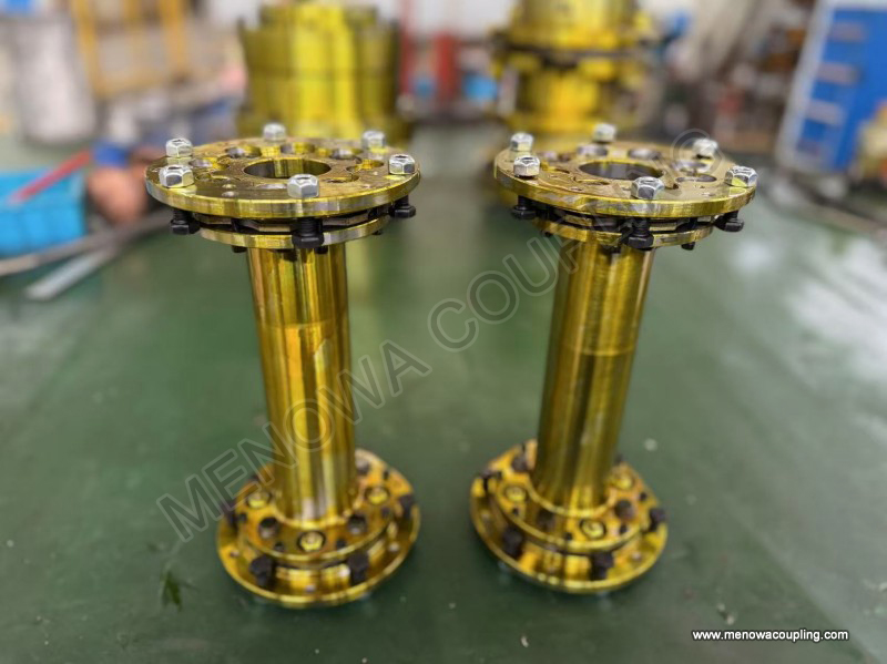
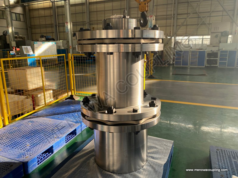
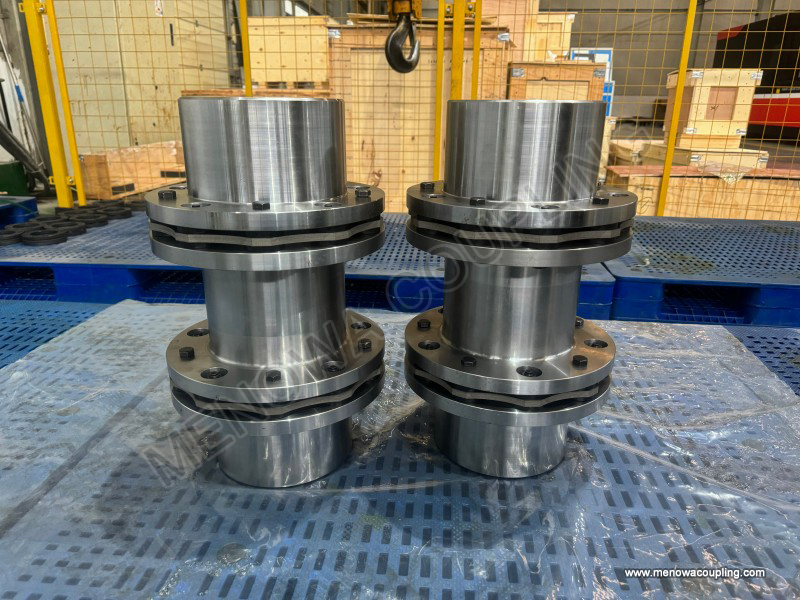
Some flexible diaphragm couplings are equipped with spacer components, also known as intermediate sleeves, which are mainly used in long-distance shaft connection scenarios and special working condition environments. The spacer is a cylindrical hollow structural part with high rigidity and light weight, usually made of high-strength lightweight alloy materials. Its two ends are respectively connected with two sets of diaphragm groups and hubs, which can increase the axial spacing between the driving shaft and the driven shaft. For mechanical equipment with a large distance between the power end and the execution end, the spacer structure can effectively solve the problem of difficult shaft connection, and can further improve the axial misalignment compensation ability of the coupling. The surface of the spacer is processed with smooth and anti-corrosion treatment, which can resist the erosion of humid, dusty and slightly corrosive media in the industrial working environment and maintain structural integrity and dimensional stability for a long time.
In terms of mechanical performance, the high-rigidity design of the spacer will not cause torque transmission loss. It can cooperate with the double-sided diaphragm group to form a dual-flexible compensation structure, which significantly improves the coupling's adaptability to complex misalignment working conditions. At the same time, the hollow structure of the spacer effectively reduces the overall weight of the coupling, avoids excessive rotational inertia caused by overweight components during high-speed operation, reduces the operating load of the equipment, and improves the overall operating efficiency of the transmission system. For some ultra-high-speed rotating equipment, the dynamic balance precision of the spacer is strictly controlled during processing to ensure that no additional eccentric vibration is generated during high-speed rotation, which guarantees the smooth operation of the entire mechanical system.
Positioning auxiliary components are also important structural parts of flexible diaphragm couplings, including positioning rings and limit gaskets, which are mainly used to ensure the assembly accuracy and operating safety of the coupling. The positioning ring is installed at the matching position of the hub and the shaft, which can accurately limit the axial installation position of the coupling, avoid axial displacement and deviation of the coupling during assembly, and ensure the coaxiality of the driving shaft and the driven shaft in the initial installation state. The limit gaskets are arranged between the diaphragm group and the hub, and between the layers of the diaphragm group. On the premise of not affecting the elastic deformation of the diaphragm, they can limit the excessive deformation range of the diaphragm, prevent permanent structural damage caused by over-deformation of the diaphragm under extreme misalignment or overload working conditions, and play a reliable protection role.
These auxiliary positioning components have extremely high matching precision, with tiny dimensional tolerances, which can effectively eliminate assembly errors and improve the overall installation precision of the coupling. In the long-term operation process, they can resist the cumulative displacement of components caused by mechanical vibration, maintain the relative position stability of each structural part of the coupling, and avoid transmission failure caused by component displacement. Although the auxiliary components do not directly participate in torque transmission and flexible compensation, they optimize the overall structural coordination of the coupling, improve the operating safety margin and service stability, and are an important part that cannot be ignored in the complete coupling structure.
The collaborative operation of all components endows the flexible diaphragm coupling with unique superior performance in industrial transmission. The high-rigidity hub ensures stable input and output of torque, the multi-layer metal diaphragm group realizes precise flexible compensation of various shaft misalignments, the high-strength fastening components maintain the integrity and tightness of the overall structure, the spacer components adapt to long-distance connection working conditions, and the positioning auxiliary components guarantee assembly precision and operating safety. Different from traditional transmission couplings, the all-metal structural design of flexible diaphragm couplings avoids the aging, deformation and failure problems of non-metal elastic components, and has excellent adaptability to high temperature, low temperature, dry and dusty working environments. The pure elastic deformation working mode without friction and wear realizes maintenance-free operation in the whole life cycle under normal working conditions, greatly reducing the later maintenance cost and equipment downtime loss of mechanical equipment.
In practical industrial applications, the structural matching of each component will be optimized according to different working condition parameters such as transmission torque, operating speed, misalignment range and ambient temperature. The thickness and number of diaphragm layers, the size of hub keyway, the strength grade of fastening bolts and the length of spacers will all be adjusted adaptively to ensure that the coupling can maintain efficient, stable and safe operating state in different complex working environments. The reasonable structural design and precise component matching make flexible diaphragm couplings widely used in precision machine tools, power generation equipment, fluid machinery, compressor units and other high-end industrial fields, providing reliable basic guarantee for the stable operation of mechanical transmission systems.
Post Date: May 25, 2026
https://www.menowacoupling.com/china-coupling/parts-of-flexible-diaphragm-coupling.html
Products

Tags
Related Articles
Specification of Flexible Diaphragm Coupling
Flexible diaphragm couplings represent a pivotal category of metal elastic transmission components widely adopted in high-precision mechanical power transmission systems, serving the core function of connecting driving and driven shafts to achieve stable torque transmission while accommodating inevitable shaft misalignm…Classification of Flexible Diaphragm Coupling
Flexible diaphragm couplings are essential components in modern mechanical transmission systems, designed to connect two shafts while compensating for relative displacements caused by manufacturing errors, installation deviations, thermal expansion, or operational vibrations. Unlike rigid couplings that require precise …Flexible Diaphragm Coupling Factory
A flexible diaphragm coupling factory is a specialized manufacturing facility dedicated to producing high-performance flexible diaphragm couplings, which are essential mechanical components used to connect two rotating shafts in various industrial applications. These couplings play a critical role in transmitting torque…Flexible Diaphragm Coupling Manufacture
Flexible diaphragm couplings stand as critical components in modern power transmission systems, bridging driving and driven shafts while accommodating misalignment, absorbing vibration, and ensuring efficient torque delivery across diverse industrial scenarios. The manufacture of these precision components integrates ma…Types of Diaphragm Coupling
Diaphragm couplings stand as a vital category of flexible metal couplings widely utilized in modern mechanical power transmission systems, designed to connect driving and driven shafts while delivering stable torque transfer and accommodating various forms of shaft misalignment through the elastic deformation of metal d…Structure of Flexible Diaphragm Coupling
Flexible diaphragm coupling serves as a vital mechanical transmission component widely applied in high-precision and high-speed mechanical transmission systems, relying on elastic deformation of metal diaphragm components to realize torque transmission and shaft misalignment compensation. Different from traditional flex…
 WeChat
 WhatsApp