Dimensions of Flexible Diaphragm Coupling
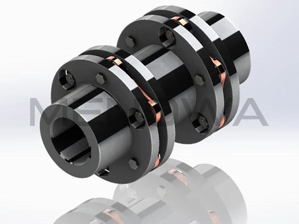
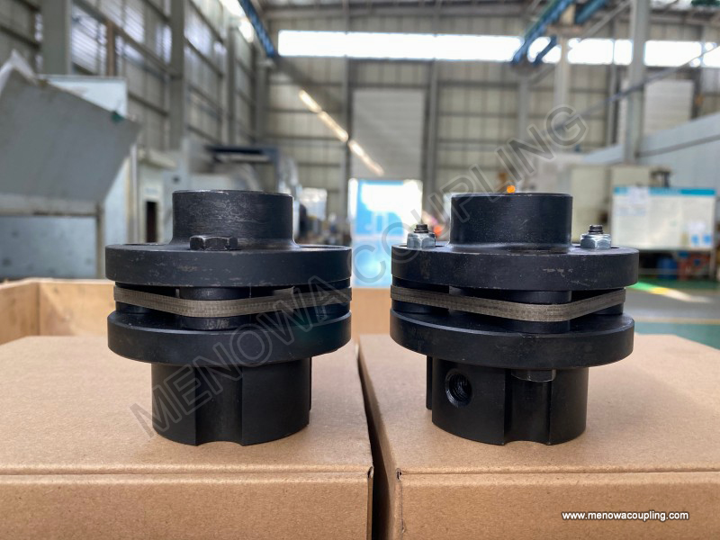
The flexible diaphragm coupling is a high-performance metal elastic flexible coupling that plays a crucial role in connecting two rotating shafts in industrial machinery, enabling efficient torque transmission while accommodating various types of misalignment between the shafts. Unlike many other coupling types that rely on rubber or plastic elastomers or require continuous lubrication, this coupling uses metal elastic elements, specifically diaphragms made of thin stainless steel plates or other high-strength metal materials, to achieve flexible connection and deviation compensation. The dimensions of a flexible diaphragm coupling are not arbitrary; they are carefully designed and selected based on the specific working conditions, transmission requirements, and environmental factors of the application. Every dimension, from the inner diameter of the shaft hole to the total length of the coupling, from the thickness of the diaphragm to the diameter of the connecting bolts, has a direct impact on the coupling’s performance, service life, and compatibility with the connected equipment. Understanding the dimensions of flexible diaphragm couplings is essential for engineers, technicians, and procurement personnel involved in industrial machinery design, installation, and maintenance, as it ensures that the selected coupling can meet the operational needs of the equipment while maintaining stability and reliability.
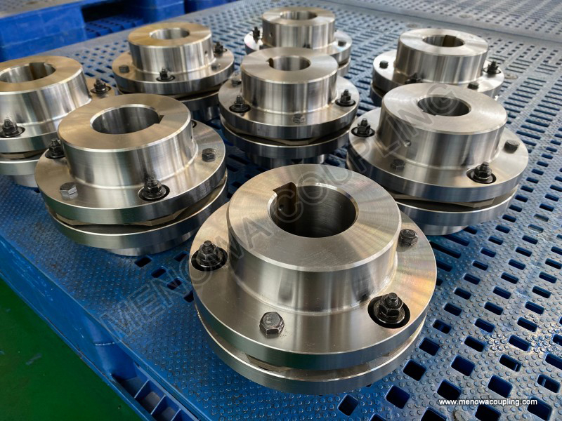
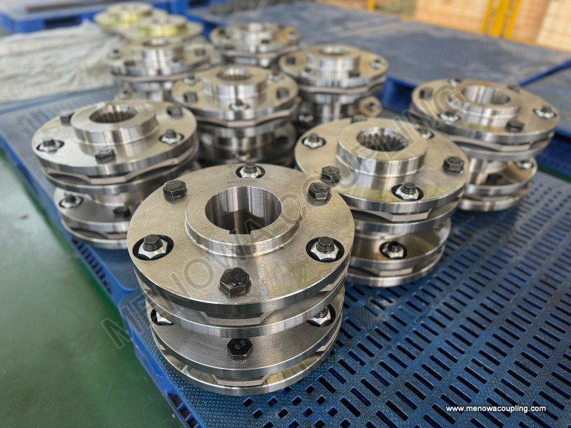
At the core of the flexible diaphragm coupling’s dimensional design are the parameters related to the shaft connection, as these directly determine how the coupling interfaces with the driving and driven shafts. The inner diameter of the shaft hole, often denoted as d1 and d2 for the two halves of the coupling, is one of the most fundamental dimensions. This dimension must precisely match the outer diameter of the shafts it connects to ensure a secure and stable fit. A shaft hole that is too large will result in loose connection, leading to vibration, noise, and even damage to the coupling or shafts during operation; conversely, a shaft hole that is too small will make installation difficult and may cause deformation of the coupling or shafts. The range of the inner diameter varies widely depending on the application, from small sizes suitable for servo motors and precision machinery to large diameters designed for heavy-duty equipment such as turbines and compressors. For example, small flexible diaphragm couplings used in precision machine tools may have inner diameters ranging from a few millimeters to around 50 millimeters, while those used in large industrial pumps or turbines can have inner diameters exceeding 200 millimeters. In addition to the inner diameter, the length of the shaft hole, referred to as L1 and L2, is another critical dimension related to the shaft connection. This dimension represents the depth to which the shafts are inserted into the coupling halves, and it must be compatible with the effective length of the shaft ends. If the shaft hole length is too short, the contact area between the shaft and the coupling will be insufficient, leading to uneven stress distribution and potential failure at the connection point; if it is too long, it may cause unnecessary space occupation and increase the overall weight of the coupling assembly. The length of the shaft hole is often designed in accordance with industry standards or the specific requirements of the equipment’s shaft ends, ensuring that the connection is both secure and efficient.
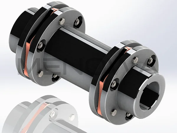
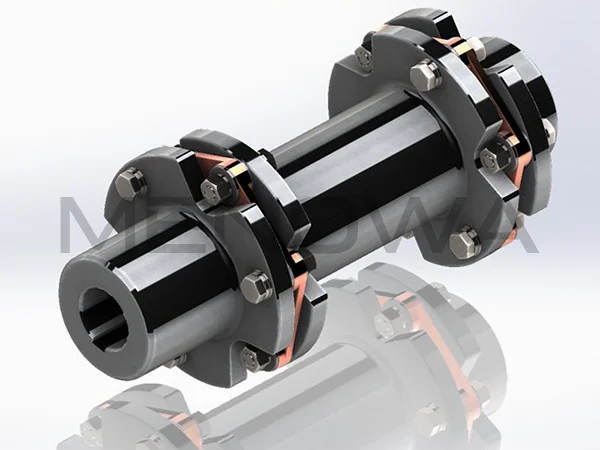
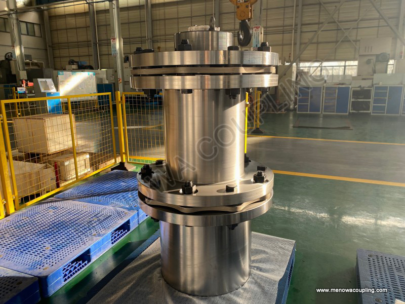
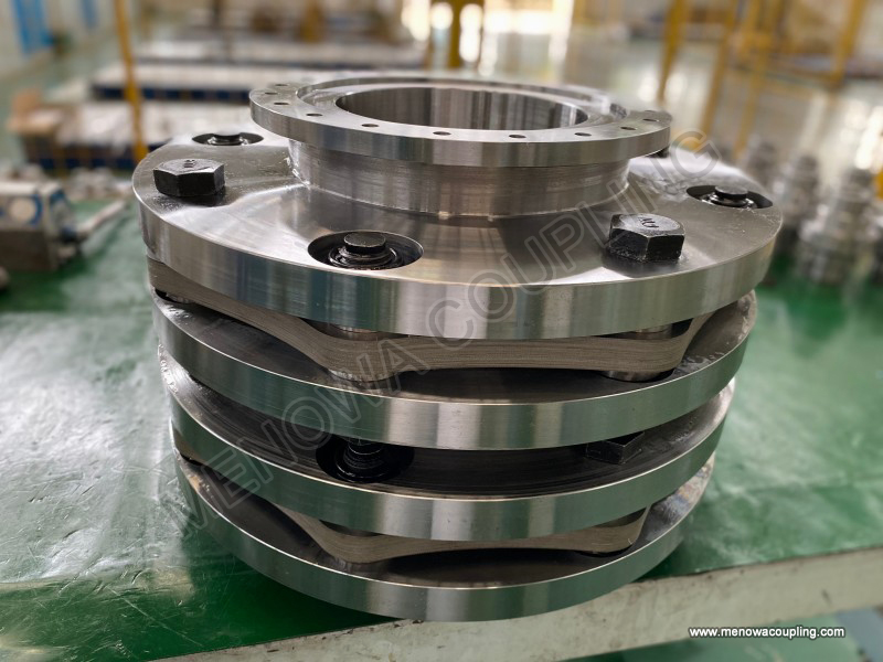
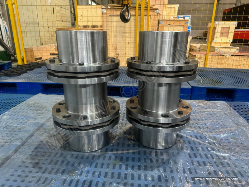
Another key set of dimensions in flexible diaphragm couplings is the overall structural dimensions, which include the maximum outer diameter, the total length of the coupling, and the distance between the diaphragms (for multi-diaphragm designs). The maximum outer diameter, denoted as D, is the largest diameter of the coupling during rotation, and it is a critical factor in determining the installation space required. This dimension must be carefully considered to ensure that the coupling does not interfere with other components in the equipment, such as casings, bearings, or other transmission parts. The outer diameter is closely related to the torque-carrying capacity of the coupling; generally, larger outer diameters correspond to higher torque capacities, as they provide a larger moment arm for torque transmission and allow for thicker or more robust diaphragm designs. However, increasing the outer diameter also increases the centrifugal force acting on the coupling during high-speed rotation, which can affect the stability and service life of the coupling. Therefore, the outer diameter must be balanced between torque capacity and centrifugal force constraints. The total length of the coupling, denoted as L, is the distance between the end faces of the two shaft holes, and it determines the overall space occupied by the coupling in the equipment. This dimension is influenced by the distance between the two shafts (shaft spacing) and the axial compensation requirement of the coupling. Axial compensation refers to the coupling’s ability to accommodate relative axial movement between the two shafts, which may be caused by thermal expansion, vibration, or installation errors. The total length of the coupling must be sufficient to provide the necessary axial compensation space while ensuring that the coupling can be installed within the available space of the equipment. For multi-diaphragm couplings, the distance between the diaphragms is an additional critical dimension; this distance affects the coupling’s ability to compensate for angular and radial misalignment, as well as its torsional stiffness. A larger distance between diaphragms generally improves the coupling’s deviation compensation capability but may reduce its torsional stiffness, so this dimension must be optimized based on the specific application requirements.
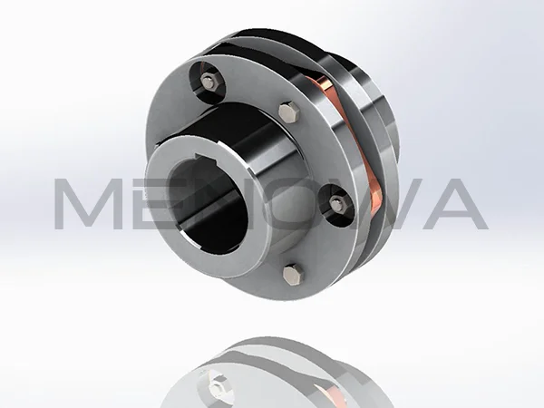
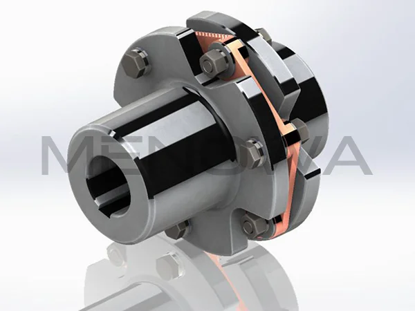
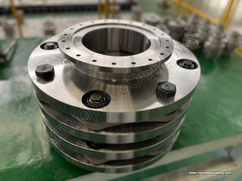
The dimensions of the diaphragm itself are among the most critical factors affecting the performance of the flexible diaphragm coupling, as the diaphragm is the core elastic element responsible for torque transmission and deviation compensation. The diaphragm is typically a thin, circular metal plate with a series of holes around its circumference for connecting to the coupling halves via bolts. The thickness of the diaphragm, denoted as t, is a key dimension that directly impacts its elastic deformation capacity, torque-carrying capacity, and fatigue life. Thicker diaphragms have higher torsional stiffness and torque-carrying capacity but lower elastic deformation capacity, making them suitable for applications with high torque and small deviations. Thinner diaphragms, on the other hand, have greater flexibility and can compensate for larger deviations but have lower torque-carrying capacity and may be more prone to fatigue failure under high loads. The thickness of the diaphragm is usually determined by the material properties (such as tensile strength and fatigue limit) and the required torque and deviation compensation requirements. In addition to thickness, the diameter of the diaphragm, the number and size of the bolt holes, and the shape of the diaphragm (such as flat, corrugated, or slotted) are also important dimensional parameters. The diameter of the diaphragm is closely related to the outer diameter of the coupling; it must be large enough to accommodate the bolt holes and provide sufficient area for torque transmission, while remaining within the overall outer diameter constraint. The number and size of the bolt holes are determined by the torque-carrying requirement and the size of the connecting bolts; more and larger bolts can transmit higher torque but may reduce the diaphragm’s structural integrity. The shape of the diaphragm is designed to optimize its elastic deformation characteristics; for example, corrugated diaphragms have better flexibility and deviation compensation capability compared to flat diaphragms, as the corrugations allow for greater elastic deformation without excessive stress concentration.
The dimensions of the connecting bolts and the bolt holes are also essential components of the flexible diaphragm coupling’s dimensional design, as they ensure the secure connection between the diaphragm and the coupling halves. The diameter and length of the bolts must be selected based on the torque to be transmitted and the thickness of the diaphragm and coupling halves. Bolts that are too small or too short may fail under the transmitted torque, leading to separation of the coupling components, while bolts that are too large or too long may add unnecessary weight and increase the overall size of the coupling. The bolt holes must be precisely positioned and sized to match the bolts, ensuring a tight fit that prevents loosening during operation. The spacing between the bolt holes is also a critical dimension; it must be uniform around the circumference of the diaphragm to ensure even stress distribution. Uneven spacing can lead to localized stress concentrations, which may cause the diaphragm to fail prematurely. In addition, the depth of the bolt holes and the type of thread (such as metric or imperial) must be compatible with the bolts used, ensuring a secure and reliable connection.
The selection of the correct dimensions for a flexible diaphragm coupling is not only based on the basic parameters of the equipment but also on the specific working conditions and environmental factors. One of the primary factors influencing dimensional selection is the torque requirement. The coupling must be able to transmit the maximum torque generated by the driving shaft without failure, which means that the dimensions related to torque transmission (such as outer diameter, diaphragm thickness, and bolt size) must be sufficient to handle the applied torque. The rated torque of the coupling, which is the maximum torque it can transmit continuously under normal operating conditions, is directly related to these dimensions. In addition to the rated torque, the peak torque (the maximum torque the coupling can withstand temporarily during overload) must also be considered, as this may require larger dimensions to ensure the coupling’s integrity. Another important factor is the speed of the rotating shafts. High-speed applications require couplings with smaller outer diameters to reduce centrifugal force, which can cause vibration and damage at high speeds. Therefore, for high-speed equipment such as turbines or precision motors, the coupling’s outer diameter is often minimized while maintaining the required torque capacity. The operating temperature is also a key factor; in high-temperature environments, the material properties of the coupling may change, which may require adjustments to the dimensions to ensure stability. For example, in high-temperature applications, the diaphragm thickness may need to be increased to compensate for the reduction in material strength at elevated temperatures.
Misalignment compensation requirements also play a significant role in determining the dimensions of the flexible diaphragm coupling. The coupling must be able to accommodate three types of misalignment: axial, radial, and angular. Axial misalignment refers to the relative axial movement between the two shafts, radial misalignment is the offset of the shafts’ axes in a radial direction, and angular misalignment is the angle between the two shafts’ axes. The dimensions of the coupling, particularly the total length, the distance between diaphragms (for multi-diaphragm designs), and the diaphragm thickness and shape, directly affect its ability to compensate for these misalignments. For example, multi-diaphragm couplings have a greater ability to compensate for angular and radial misalignment compared to single-diaphragm couplings, as the multiple diaphragms can deform synergistically to absorb the misalignment. The total length of the coupling also affects axial compensation; a longer coupling can accommodate greater axial movement. Therefore, applications with significant misalignment require couplings with specific dimensions optimized for deviation compensation.
The material of the coupling components also influences the dimensional design. Flexible diaphragm couplings are typically made of high-strength materials such as stainless steel, aluminum alloy, or titanium alloy, each with different mechanical properties. Stainless steel is commonly used due to its high strength, corrosion resistance, and fatigue resistance, making it suitable for harsh environments such as chemical processing or marine applications. Aluminum alloy is lighter than stainless steel, making it ideal for high-speed applications where weight reduction is important. Titanium alloy has excellent strength-to-weight ratio and corrosion resistance, making it suitable for aerospace and high-performance industrial applications. The material’s properties, such as tensile strength, yield strength, and fatigue limit, determine the minimum dimensions required to achieve the desired performance. For example, a coupling made of a material with lower tensile strength will require larger dimensions (such as thicker diaphragms or larger outer diameter) to transmit the same torque as a coupling made of a higher-strength material.
In addition to the functional dimensions, the dimensional tolerances of the flexible diaphragm coupling are also critical. Tolerances refer to the allowable deviation from the nominal dimension, and they ensure that the coupling components fit together properly and function as intended. Tight tolerances are required for critical dimensions such as the inner diameter of the shaft hole, the position of the bolt holes, and the thickness of the diaphragm. For example, the inner diameter of the shaft hole must have a tight tolerance to ensure a proper fit with the shaft; excessive tolerance can lead to loose connection and vibration. The position of the bolt holes must also have high precision to ensure that the bolts align correctly with the diaphragm and coupling halves, preventing stress concentration and ensuring even torque distribution. The tolerances are typically specified in accordance with industry standards, such as ISO or ANSI, and they vary depending on the application’s precision requirements. High-precision applications, such as precision machine tools or aerospace equipment, require tighter tolerances than general industrial applications.
The application of flexible diaphragm couplings spans a wide range of industries, including petrochemical, power generation, aerospace, heavy machinery, precision manufacturing, and marine propulsion, each with unique dimensional requirements. In the petrochemical industry, couplings used in pumps and compressors must be designed to handle high temperatures, corrosive environments, and high torques, which requires larger outer diameters, thicker diaphragms, and corrosion-resistant materials. In the power generation industry, couplings connecting steam turbines and generators must accommodate thermal expansion and high speeds, leading to dimensions optimized for axial compensation and low centrifugal force. In the aerospace industry, lightweight and compact dimensions are critical, so couplings are often made of titanium alloy with minimal outer diameter and total length while maintaining high torque capacity. In precision manufacturing, such as CNC machine tools, couplings must have high precision and low torsional stiffness to ensure accurate torque transmission and positioning, which requires tight dimensional tolerances and optimized diaphragm dimensions. In marine propulsion, couplings must withstand harsh marine environments, including saltwater corrosion and high vibrations, so dimensions are designed to ensure durability and stability under these conditions.
Proper dimensional selection and design of flexible diaphragm couplings are essential to ensure their reliable operation and long service life. A coupling with incorrect dimensions may fail prematurely, leading to equipment downtime, increased maintenance costs, and potential safety hazards. Therefore, it is crucial to conduct a thorough analysis of the application requirements, including torque, speed, misalignment, operating temperature, and installation space, before selecting or designing a flexible diaphragm coupling. Engineers must also consider the material properties, dimensional tolerances, and industry standards to ensure that the coupling meets all performance requirements. In addition, regular inspection and maintenance of the coupling, including checking for dimensional changes due to wear or deformation, are important to ensure that the coupling continues to function properly over time. For example, wear on the shaft hole or diaphragm may change the critical dimensions, leading to reduced performance or failure, so timely replacement of worn components is necessary.
In conclusion, the dimensions of flexible diaphragm couplings are a complex interplay of functional requirements, material properties, and operating conditions. Every dimension, from the inner diameter of the shaft hole to the thickness of the diaphragm, from the outer diameter to the total length, plays a critical role in determining the coupling’s performance, compatibility, and reliability. Understanding these dimensions and their impact on the coupling’s function is essential for anyone involved in the design, selection, installation, or maintenance of industrial machinery. By carefully considering the specific application requirements and optimizing the dimensions accordingly, engineers can ensure that the flexible diaphragm coupling provides efficient, reliable, and long-lasting service, contributing to the overall performance and productivity of the equipment it connects. As industrial technology continues to advance, the dimensional design of flexible diaphragm couplings will continue to evolve, with a focus on improving performance, reducing weight, and enhancing compatibility with a wide range of applications.
Post Date: Apr 29, 2026
https://www.menowacoupling.com/china-coupling/dimensions-of-flexible-diaphragm-coupling.html
Products

Tags
Related Articles
Size Chart of Flexible Diaphragm Coupling
The size chart of flexible diaphragm coupling is an essential reference tool for engineers, procurement personnel, and maintenance technicians in various industrial fields, as it provides precise dimensional parameters and matching guidelines to ensure the coupling can perfectly adapt to different equipment and working …Types of Shim Pack Coupling
Shim pack couplings stand as a vital category of metal flexible transmission components widely applied in modern industrial mechanical shaft connection systems, serving the core purpose of stable torque transmission between driving and driven equipment while effectively absorbing and compensating for various minor misal…Flexible Diaphragm Coupling Exporter
In the global industrial transmission system, flexible diaphragm couplings have become an indispensable core component, widely used in various fields that require high-precision, high-reliability torque transmission. As a professional exporter focusing on flexible diaphragm couplings, we are committed to providing high-…Flexible Diaphragm Coupling Factory
A flexible diaphragm coupling factory is a specialized manufacturing facility dedicated to producing high-performance flexible diaphragm couplings, which are essential mechanical components used to connect two rotating shafts in various industrial applications. These couplings play a critical role in transmitting torque…Flexible Diaphragm Coupling Manufacture
Flexible diaphragm couplings stand as critical components in modern power transmission systems, bridging driving and driven shafts while accommodating misalignment, absorbing vibration, and ensuring efficient torque delivery across diverse industrial scenarios. The manufacture of these precision components integrates ma…Types of Diaphragm Coupling
Diaphragm couplings stand as a vital category of flexible metal couplings widely utilized in modern mechanical power transmission systems, designed to connect driving and driven shafts while delivering stable torque transfer and accommodating various forms of shaft misalignment through the elastic deformation of metal d…Characteristics of Flexible Diaphragm Coupling
A flexible diaphragm coupling is a high-performance flexible coupling that uses metal elastic elements to connect two rotating shafts in industrial machinery, enabling efficient torque transmission while accommodating various types of misalignment between the shafts. Unlike many other coupling types that rely on rubber …What is Shim Pack Coupling
In the vast and interconnected field of mechanical power transmission systems, the reliable connection between rotating shafts stands as one of the most foundational and functionally critical elements for the stable operation of all types of industrial machinery and mechanical equipment. Every rotating mechanical device…
 WeChat
 WhatsApp