Gap Chart of Flexible Diaphragm Coupling
The gap chart of flexible diaphragm couplings serves as a core technical reference that quantifies the spatial clearance parameters between key structural components under diverse operating conditions, laying a foundational role in installation calibration, operational condition monitoring, and service life prediction of shaft transmission systems. Unlike rigid coupling structures that pursue zero clearance assembly, flexible diaphragm couplings rely on reasonable and controllable internal gaps to realize elastic deformation, misalignment compensation, and stable torque transmission, making gap parameter management the key to balancing transmission accuracy and structural flexibility. All gap data recorded in professional gap charts are derived from mechanical deformation simulation, bench test verification, and long-term industrial operation accumulation, covering static assembly gaps, dynamic operating gaps, and limit allowable gaps under extreme working conditions, providing standardized technical criteria for engineering application and equipment maintenance.
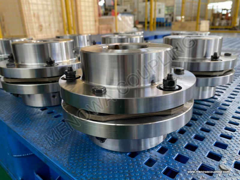
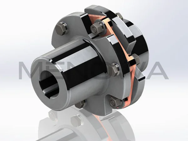
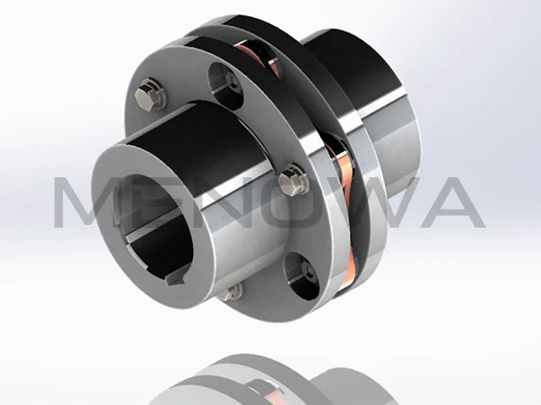
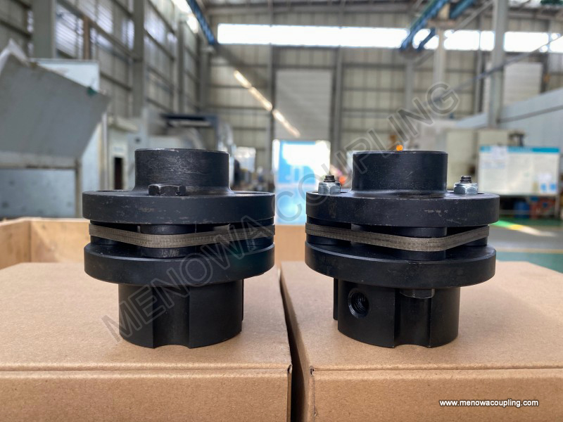
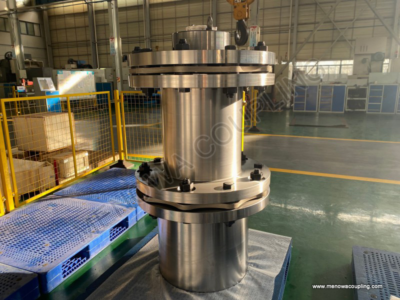
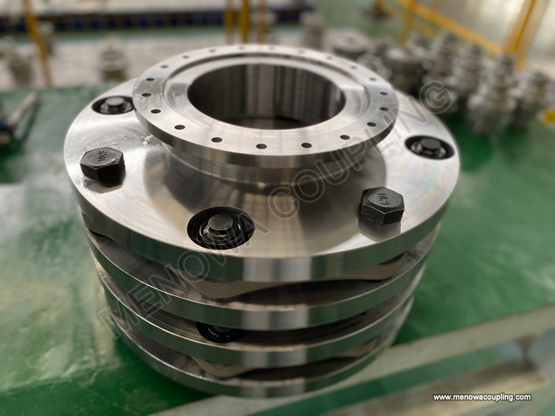
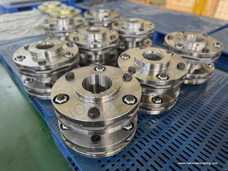
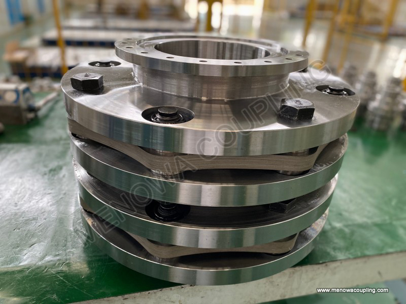
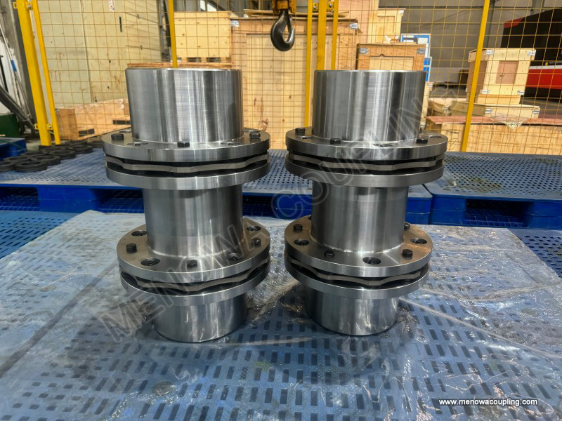
To fully understand the practical value of the flexible diaphragm coupling gap chart, it is essential to clarify the core structural components that determine gap distribution and their interactive relationships. A typical flexible diaphragm coupling is composed of driving flanges, driven flanges, stacked metal diaphragm groups, and connecting fasteners, with gaps mainly concentrated between the diaphragm and flanges, between stacked diaphragm sheets, and between fasteners and mounting holes. In the static assembly state without torque load and rotational operation, the gap chart defines the basic assembly clearance range for each part, which is designed to reserve sufficient deformation space for the diaphragm while avoiding excessive assembly looseness. The static gap parameters are formulated based on the elastic modulus and structural thickness of the diaphragm material. Thin and high-strength metal diaphragms require precise small gaps to prevent lateral displacement during static placement, while multi-layer stacked diaphragm groups need tiny interlayer gaps to eliminate assembly stress and ensure synchronous elastic deformation during operation.
Dynamic operating gaps are the most critical data module in the flexible diaphragm coupling gap chart, reflecting the real-time gap variation law of coupling components under torque transmission, high-speed rotation, and misalignment compensation. When the coupling starts to operate and bear torque load, the metal diaphragm undergoes elastic bending and torsional deformation, and the internal structural gaps will change dynamically with the deformation degree. Under rated working conditions, the gap chart shows a regular and stable fluctuation range of gaps. The gaps on the torque-bearing side of the diaphragm decrease slightly, while the gaps on the flexible deformation side increase moderately, forming a balanced stress distribution state. This dynamic gap change is a normal working characteristic of flexible diaphragm couplings, and the standard gap fluctuation range defined in the chart ensures that the diaphragm always works within the elastic deformation limit without plastic deformation or structural failure.
The gap chart also elaborates on the gap variation characteristics of flexible diaphragm couplings under different misalignment states, which is of great guiding significance for on-site fault diagnosis. In the case of pure axial misalignment, the diaphragm produces axial stretching and bending deformation, the overall axial gap of the coupling increases uniformly, and the radial gap remains relatively stable. In the case of pure radial misalignment caused by shaft offset, the diaphragm produces asymmetric deformation, resulting in alternating increase and decrease of circumferential gaps, and the gap fluctuation amplitude is positively correlated with the misalignment degree. In the case of angular misalignment where the two shafts are not parallel, the gap difference at both ends of the coupling increases significantly, and the gap fluctuation frequency is consistent with the equipment rotation frequency. By comparing the on-site measured gap data with the standard data in the gap chart, engineers can quickly judge the type and degree of shaft misalignment, so as to carry out targeted alignment correction and avoid long-term operation of the coupling under excessive misalignment.
Working speed is an important factor affecting dynamic gaps, and the gap chart summarizes the gap variation rules of flexible diaphragm couplings in low-speed, medium-speed, and high-speed operating intervals. At low rotational speeds, the centrifugal force of structural components is weak, the diaphragm deformation is mainly affected by torque load, and the dynamic gap is close to the static assembly gap with small fluctuation amplitude. With the increase of rotational speed, the diaphragm and fasteners produce slight centrifugal expansion, the local gaps decrease slightly, and the overall gap uniformity is still maintained within the standard range. When operating at ultra-high speed, the micro-deformation of the diaphragm and flanges increases, and the gap chart marks the high-speed allowable gap threshold. Once the gap is lower than the limit value, the structural components will have friction and collision, resulting in increased operating temperature, accelerated wear, and even transmission jitter. Therefore, the high-speed interval gap parameters in the chart are the key basis for selecting coupling specifications for high-speed rotating equipment such as fans, pumps, and turbine transmission systems.
Load fluctuation is another core factor that changes the gap state of flexible diaphragm couplings, and the gap chart records the gap response characteristics under stable load, intermittent load, and impact load conditions. Under stable rated load, the coupling gap presents a regular cyclic change with stable amplitude and no abnormal deviation, which is the optimal operating state of the equipment. Under intermittent load with frequent load switching, the diaphragm deforms repeatedly, and the dynamic gap fluctuates periodically with load changes. Long-term operation in this state will cause tiny fatigue gaps on the diaphragm surface, leading to gradual increase of overall structural gaps. Under instantaneous impact load, the diaphragm produces transient large deformation, the local gap instantaneously exceeds the standard dynamic range, and the gap chart clearly defines the maximum allowable impact gap. Excessive instantaneous gap deviation will cause irreversible micro-damage to the diaphragm material, reducing the structural elasticity and compensation performance of the coupling.
Temperature variation in the operating environment will cause thermal expansion and contraction of coupling components, thus changing the internal gap, and the gap chart is equipped with temperature compensation gap correction data for different working temperature ranges. At normal ambient temperature, the standard gap parameters are applicable to most conventional industrial scenarios. In high-temperature working environments, the metal components of the coupling expand thermally, and the internal gaps decrease accordingly. The gap chart provides graded gap correction values corresponding to different temperature gradients, guiding personnel to appropriately reserve assembly gaps during high-temperature equipment installation to prevent structural jamming caused by thermal expansion gap reduction. In low-temperature environments, the component shrinkage leads to increased gaps, and the chart defines the low-temperature limit gap range to avoid excessive gaps causing vibration and impact during equipment operation.
The limit gap parameters in the flexible diaphragm coupling gap chart are critical indicators for judging equipment aging and failure, including maximum allowable assembly gap, maximum dynamic fluctuation gap, and fatigue failure threshold gap. After long-term operation, the diaphragm material will produce fatigue creep, the structural elasticity will decline, and the internal assembly gaps will gradually increase. When the measured gap exceeds the limit value specified in the chart, it indicates that the coupling has suffered obvious aging failure, and continuous operation will lead to increased transmission error, intensified equipment vibration, and even diaphragm fracture and torque transmission interruption. The gap chart also sorts out the corresponding relationship between gap deviation degree and fault severity, providing a quantitative basis for formulating equipment maintenance cycles and replacement plans. Regular gap detection and comparison with chart standards can realize predictive maintenance of couplings, effectively reducing unplanned downtime of production equipment.
In practical engineering applications, the accurate use of gap charts can effectively improve the installation accuracy and operational stability of flexible diaphragm couplings. During equipment commissioning, staff can adjust the assembly state by referring to the static gap standard in the chart to eliminate assembly errors. During daily equipment inspection, dynamic gap monitoring data can be used to compare with the chart’s dynamic gap range to timely find hidden problems such as shaft misalignment, loose fasteners, and diaphragm fatigue. For equipment working under special working conditions such as variable speed, variable load, and extreme temperature, the graded gap parameters in the chart can guide personalized installation and debugging schemes to ensure that the coupling always maintains optimal flexible transmission performance in complex working environments.
In conclusion, the gap chart of flexible diaphragm couplings is a systematic and standardized technical data system that runs through the whole life cycle of coupling installation, operation, and maintenance. It quantitatively reveals the gap variation rules of coupling structures under different working conditions, clarifies the reasonable range and limit threshold of various gaps, and solves the technical problems of difficult quantitative judgment of coupling assembly quality and operating state. Mastering the core parameters and variation laws of the gap chart is crucial to giving full play to the advantages of flexible diaphragm couplings such as high efficiency, low wear, and maintenance-free operation, ensuring the long-term stable and reliable operation of mechanical transmission systems in various industrial scenarios. With the continuous upgrading of mechanical transmission technology, the gap parameter system of flexible diaphragm couplings is also constantly optimized, providing more accurate and refined technical support for high-precision and high-stability mechanical transmission engineering.
Post Date: May 25, 2026
https://www.menowacoupling.com/china-coupling/gap-chart-of-flexible-diaphragm-coupling.html
Products

Tags
Related Articles
Types of Flexible Diaphragm Coupling
Types of Flexible Diaphragm CouplingFlexible diaphragm couplings are essential mechanical transmission components designed to connect two rotating shafts while compensating for various forms of shaft misalignment, absorbing vibration, and ensuring precise and efficient torque transmission in mechanical systems. Unlike r…Components of Flexible Diaphragm Coupling
A flexible diaphragm coupling is a high-performance mechanical component widely used in various industrial applications to connect two shafts and transmit torque while compensating for relative displacements between them. Unlike rigid couplings that require precise alignment, flexible diaphragm couplings utilize the ela…Flexible Diaphragm Coupling Price
In the realm of industrial power transmission, flexible diaphragm couplings stand out as a critical component, valued for their ability to connect two rotating shafts while compensating for misalignments, absorbing minor vibrations, and ensuring efficient torque transfer. As businesses across various industries—from ma…Size Chart of Flexible Diaphragm Coupling
The size chart of flexible diaphragm coupling is an essential reference tool for engineers, procurement personnel, and maintenance technicians in various industrial fields, as it provides precise dimensional parameters and matching guidelines to ensure the coupling can perfectly adapt to different equipment and working …Types of Shim Pack Coupling
Shim pack couplings stand as a vital category of metal flexible transmission components widely applied in modern industrial mechanical shaft connection systems, serving the core purpose of stable torque transmission between driving and driven equipment while effectively absorbing and compensating for various minor misal…Uses of Flexible Diaphragm Coupling
In modern mechanical transmission systems, the stable connection and efficient torque transmission between rotating shafts are the core guarantees for the normal operation of all kinds of mechanical equipment. As a high-performance metal flexible transmission component, flexible diaphragm coupling has gradually become a…
 WeChat
 WhatsApp