Curved Tooth Coupling Exporter
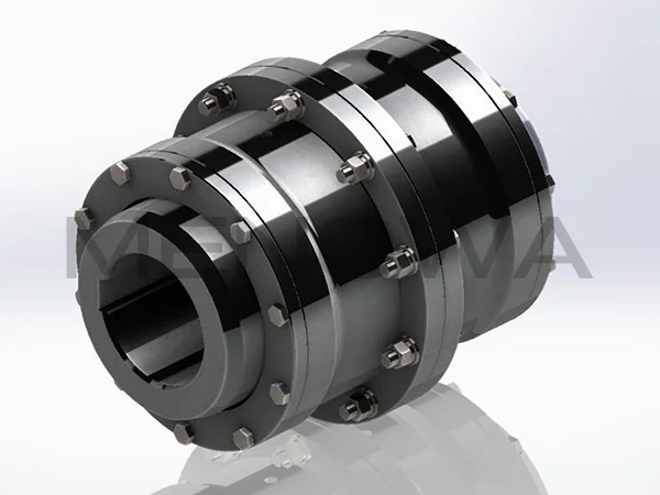
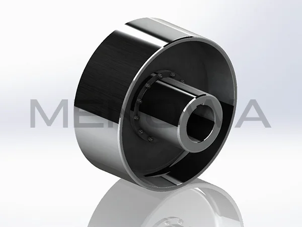
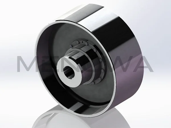
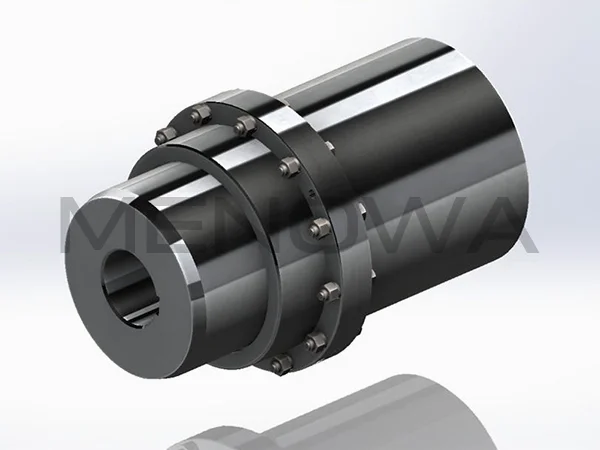
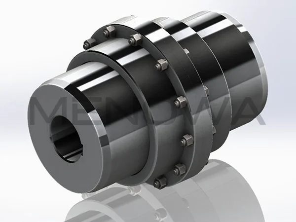
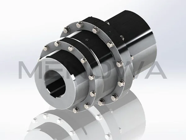
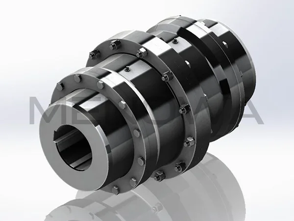
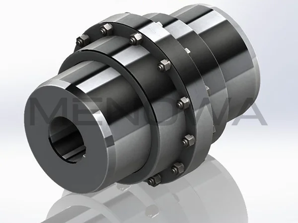
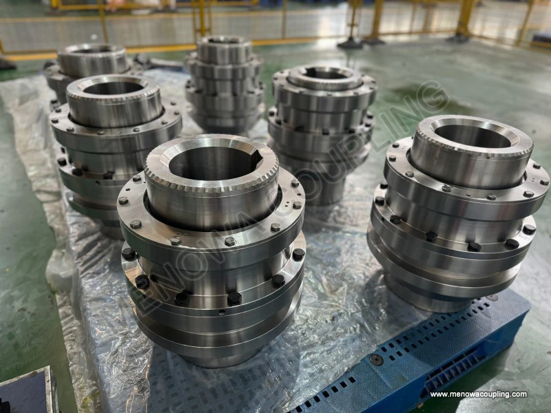
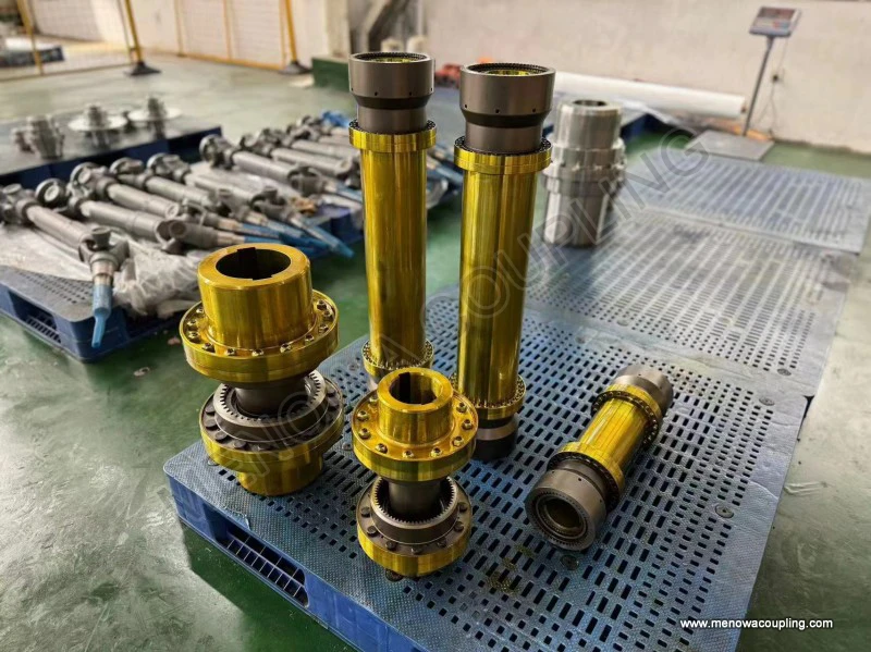
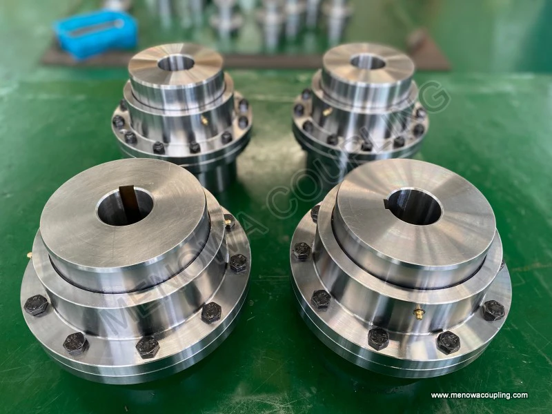
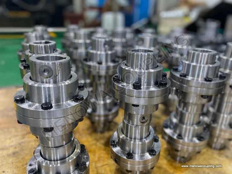
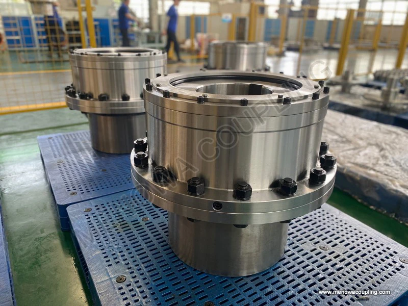
Curved tooth couplings, also widely known as crowned tooth gear couplings, occupy a distinctive place in the landscape of industrial power transmission. Unlike their straight-sided predecessors, these couplings feature teeth that are machined with a curved, crowned profile along the hub, a refinement that has fundamentally changed the way engineers approach the challenge of connecting rotating shafts that are not perfectly aligned. For anyone engaged in exporting industrial components to international markets, a genuine grasp of this product is not merely an academic exercise; it is a commercial necessity. The decisions made at the selection stage influence equipment reliability, maintenance intervals, energy efficiency, and ultimately the reputation of the machinery manufacturer in the eyes of end users across the globe.
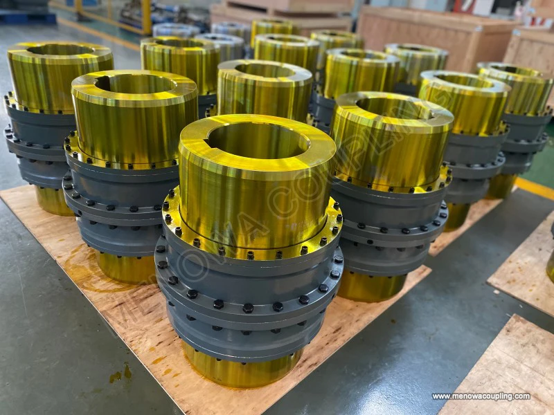
To appreciate why the curved tooth geometry matters, it is useful to consider the physics of misalignment. In any real installation, the two shafts joined by a coupling are rarely in perfect coaxial alignment. Angular offset, parallel offset, and axial displacement all occur to some degree, arising from manufacturing tolerances, thermal expansion, foundation settlement, frame flexure under load, or the gradual wear of bearings and supports. A rigid coupling simply cannot accommodate these deviations without generating enormous internal stresses that accelerate fatigue and lead to premature failure of the machine. A straight-toothed gear coupling can tolerate more misalignment than a rigid element, but it does so at the cost of concentrated edge loading. When a straight tooth tips out of parallel with its mating tooth, the line of contact collapses toward the edge of the tooth, creating severe stress concentrations and rapid localized wear that progressively destroys the working surface.
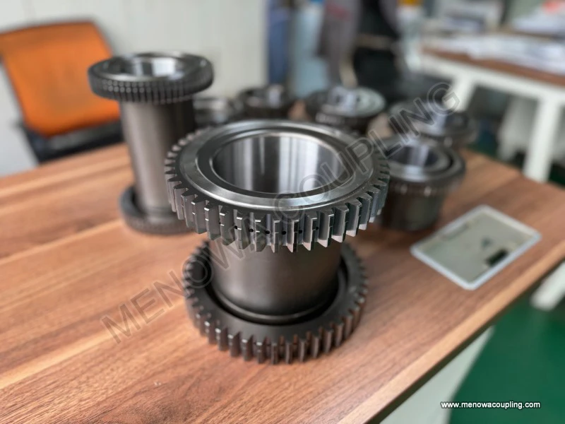
The curved tooth profile addresses this weakness elegantly. By crowning the tooth along its length, the manufacturer ensures that the contact area remains near the centre of the tooth face even when the shafts are angularly displaced relative to each other. The coupling can therefore transmit torque smoothly while permitting a meaningful degree of angular misalignment, often on the order of one to two degrees for larger sizes, without sacrificing load-carrying capacity. This crowned geometry, combined with a properly lubricated mesh between the external teeth of the hubs and the internal teeth of the sleeve, gives the curved tooth coupling its well-earned reputation for high torque density, durability, and long service life. It is precisely these attributes that make it the coupling of choice in heavy industry, where unplanned downtime is measured not in minutes but in lost tons of production and in the real cost of restarting complex process lines.
The usage occasions for curved tooth couplings are as broad as heavy industry itself. Rolling mills in the steel sector represent one of the most demanding applications, where high torque, shock loading, and frequent reversing place extreme demands on every component in the driveline. Cement plants rely on these couplings in kiln drives, crushers, and bucket elevators, where abrasive dust, high temperatures, and continuous operation test the limits of any mechanical device. Mining operations, from overland conveyors to ball mills and slurry pumps, also depend on the curved tooth coupling to preserve alignment integrity along drive trains that may span considerable distances. Paper mills, sugar mills, marine propulsion systems, large process pumps, compressors, fans, and enclosed gear reducers all feature prominently among the applications. In each of these environments, the coupling must not only transmit power faithfully but also protect the connected equipment from the consequences of residual misalignment and axial float that would otherwise damage bearings, seals, and gear reducers.
The choice between a curved tooth coupling and alternative solutions such as elastomeric couplings or metallic disc couplings is ultimately governed by the specific operating envelope. Curved tooth couplings excel wherever torque density is paramount and space is constrained, because a gear coupling can transmit a very high torque within a comparatively small envelope relative to flexible couplings of equivalent capacity. They are also well suited to high-speed operation, provided the design is properly balanced and lubrication is adequate, and they are naturally tolerant of the moderate misalignment that accumulates in long or multi-bearing installations. By contrast, elastomeric couplings introduce torsional softness that can damp vibration and cushion shock, which is valuable in some installations but undesirable in others where precise angular phasing or synchronization is critical. Disc couplings offer near-zero backlash and high torsional stiffness, but they are generally more sensitive to misalignment and demand greater care in installation and alignment. The curved tooth coupling occupies a balanced position across this spectrum, offering a robust combination of load capacity, misalignment tolerance, serviceability, and compactness that few alternatives can match in heavy-duty service.
The selection of a curved tooth coupling follows a logical and largely standardized engineering procedure, even though the fine details may differ from one supplier's catalogue to the next. The process begins with the determination of the rated torque that the coupling must transmit. For a given application, the transmitted torque is calculated from the power and the rotational speed. In the widely used metric convention, the nominal torque in Newton-metres is given by the relationship
T = 9550 × P / n
where T is the nominal torque in Newton-metres, P is the transmitted power in kilowatts, and n is the rotational speed in revolutions per minute. For engineers working in imperial units, the equivalent expression using horsepower yields the torque in inch-pounds through the factor 63000, such that T = 63000 × HP / RPM.
This nominal torque, however, is rarely the value used directly for selection, because real applications seldom operate under perfectly steady and uniform conditions. The designer must multiply the nominal torque by an application service factor to obtain the design torque, expressed as
Td = K × T
where Td is the design torque and K is the service factor reflecting the severity of the duty. The service factor is not a single universal number but rather a composite that accounts for the type of driver, the nature of the driven load, and the expected frequency and magnitude of shock loads. A smooth-running electric motor driving a centrifugal pump at a steady speed, for example, would command a relatively modest service factor, whereas a diesel engine driving a reciprocating compressor, or a machine subjected to frequent starting, stopping, and reversing, would demand a substantially higher value. In many selection procedures, the service factor is further combined with additional allowances for starting frequency, ambient temperature, and the desired level of reliability over the design life.
Once the design torque is established, the engineer compares it with the rated torque capacity of candidate coupling sizes. The fundamental condition for a valid selection is that the design torque must be less than or equal to the rated capacity of the selected coupling, such that
Td ≤ Tc
where Tc represents the rated torque capacity of the chosen coupling size as published in the supplier's technical data. This comparison is the backbone of the entire selection exercise. Selecting a coupling too small for the duty invites premature failure through tooth fatigue and edge wear, whereas oversizing introduces unnecessary cost, weight, and envelope dimensions without any compensating engineering benefit.
Beyond torque, the selection process must address bore size and shaft engagement. The coupling must accommodate the actual shaft diameters present in the installation, and the designer must verify that the bore, keyway, or shrink-fit arrangement can transmit the full design torque without exceeding the allowable stresses at the shaft-to-hub interface. In this connection, the maximum allowable bore of each frame size frequently becomes a binding constraint. It is not uncommon for the maximum bore requirement to determine the frame size even when a smaller coupling would otherwise satisfy the torque demand, so the bore check should always be performed in parallel with the torque check rather than as an afterthought.
Speed is another critical parameter. Every coupling design has a limiting speed, sometimes defined by the maximum peripheral velocity of the gear teeth and sometimes by the balance quality achieved in manufacture. Above a certain rotational speed, centrifugal effects on the lubricant and on the unbalance of the assembly become significant, and the coupling must be balanced to an appropriate grade to avoid vibration. For high-speed applications, the engineer must confirm that the operating speed is within the published speed rating of the coupling and that the dynamic balancing specification is consistent with the machine's requirements. Ignoring this constraint is a common cause of vibration problems that are later misdiagnosed as bearing faults or foundation issues.
Axial displacement, or the free axial float that the coupling must absorb, also deserves explicit attention. Curved tooth couplings are capable of accommodating a certain amount of axial movement between the shafts, which is essential in applications where thermal growth is expected or where the driven machine is permitted to float axially. The design should specify the allowable axial travel, and the installation should provide sufficient clearance so that the internal teeth do not bottom out and generate unexpected end thrust. In some designs, the engineer may deliberately limit axial float by other elements in the drive train, in which case the coupling must be selected accordingly.
Lubrication is arguably the single most important operational factor in determining the service life of a curved tooth coupling. Most couplings of this type are supplied for grease-packed operation, in which the sleeve is filled with a high-quality coupling grease at installation and replenished at regular intervals. Some larger or high-speed units are designed for oil lubrication, either through a continuous circulation system or by a splash arrangement that relies on the internal rotation of the coupling. The choice between grease and oil lubrication depends on speed, size, operating temperature, and access for maintenance. Whatever the method, the mesh must never be allowed to run dry, because the crowned teeth rely on the formation of a hydrodynamic film between the contacting surfaces to distribute the load and prevent scuffing. Routine inspection of lubricant condition and scheduled replenishment are the most effective, and the least expensive, measures for extending coupling life.
Temperature and environment further refine the selection. In hot applications such as kiln drives or near furnaces, the operating temperature affects both the strength of the coupling material and the suitability of the lubricant and seals. In dusty environments, ingress protection becomes important, and the coupling may require improved sealing arrangements to exclude abrasive particles. In corrosive atmospheres, the choice of surface treatment and coating must be matched to the severity of the exposure. Each of these considerations should be documented as part of the selection record so that the delivered product is genuinely fit for the conditions of service, rather than simply adequate on paper.
The engineering quality of the coupling itself rests on several underlying disciplines that an international buyer should examine carefully. The teeth are typically produced by hobbing or shaping and are heat treated to achieve a hard, wear-resistant working surface while retaining sufficient core toughness. The accuracy of the tooth profile and the quality of the crowned geometry directly determine the load distribution across the face and therefore the useful life of the mesh. Backlash, which is the intentional clearance between mating teeth, must be controlled within the appropriate range for the application, because excessive backlash can cause noise and impact loads while insufficient backlash can lead to binding. For high-speed duty, the coupling should be dynamically balanced to the appropriate grade, and the balance should be verified on production units rather than assumed from the design.
From the perspective of an exporter serving international markets, the value of a curved tooth coupling extends well beyond the hardware itself. Buyers in developed and emerging markets alike increasingly demand application engineering support: they expect the supplier to confirm that the selected coupling is appropriate for their speed, torque, misalignment, and lubrication conditions, and they value a supplier who can provide clear selection guidance backed by consistent documentation. Dimensional interchangeability with existing installations is a practical concern, because many end users are replacing worn couplings on machines that are already in service and require a drop-in solution that matches the established mounting dimensions and bore configurations. Lead time and the reliability of delivery are likewise commercial factors that influence repeat business, as are the availability of spare sleeves, hubs, and seals and the quality of packaging for long-distance freight. A supplier who demonstrates competence in all of these areas is far more likely to build lasting relationships than one who competes on price alone.
For the engineer in the field, a few practical selection reminders are worth committing to memory. Always confirm the actual transmitted power and speed from the machine specification rather than from nameplate ratings that may include reserve margins. Apply a service factor that honestly reflects the severity of the duty, and do not be tempted to use a benign factor simply to justify a smaller, less expensive coupling. Check the bore and keyway capacity in conjunction with the torque capacity, because the shaft connection is frequently the weakest link in the entire assembly. Verify that the operating speed is within the coupling's speed rating and that balancing is appropriate for that speed. Confirm that the axial float requirement is satisfied. Specify a lubrication regime that matches the speed, size, and accessibility of the installation, and make sure the maintenance staff understands the replenishment schedule. Finally, document the complete selection rationale, including the calculations and the assumed service conditions, so that the reasoning can be reviewed if a problem arises and so that future replacements can be made with confidence.
In summary, the curved tooth coupling remains an indispensable element of modern industrial power transmission, prized for its high torque density, generous misalignment capacity, and robust service life. Its success rests on a clever geometric principle that transforms the ancient problem of shaft misalignment into a manageable engineering variable. For the international buyer, however, the coupling is only as good as the selection process that precedes it and the maintenance discipline that follows it. A well-chosen, well-lubricated, and correctly aligned curved tooth coupling can serve faithfully for years, protecting valuable machinery and keeping production moving. The exporter who understands this interplay of geometry, torque, speed, lubrication, and application service, and who communicates that understanding clearly to customers, will find that the product sells not merely on specifications but on the confidence it inspires.
Post Date: Oct 13, 2026
https://www.menowacoupling.com/china-coupling/curved-tooth-coupling-exporter.html
Products
Tags
Supply
Related Articles
Working Principle of Curved Tooth Coupling
The curved tooth coupling, frequently referred to in engineering literature as a crowned tooth coupling or a crowned gear coupling, belongs to the broad family of flexible shaft couplings whose purpose is to transmit mechanical power from one rotating shaft to another while accommodating the small but unavoidable errors…Material of Curved Tooth Coupling
Curved tooth couplings have emerged as one of the most reliable and versatile mechanical transmission components in the global industrial machinery sector, serving as a core connecting unit for shaft torque transmission in heavy-duty, high-speed, and misalignment-tolerant operating environments. The unique curved tooth …Characteristics of Curved Tooth Coupling
In the global industrial transmission equipment market, curved tooth couplings have emerged as a core universal transmission component, widely adopted in heavy-duty machinery, energy equipment, marine engineering, and mining industries across all regional markets. Differing from traditional straight tooth gear couplings…Gear Type Coupling Supply
Gear type couplings stand as one of the most reliable and high-performance mechanical components designed for torque transmission and shaft connection across diverse industrial mechanical systems. As a core component in power transmission machinery, these specialized couplings are engineered to connect two rotating shaf…Types of Gear Type Coupling
Gear type couplings stand as one of the most robust and reliable flexible coupling solutions in modern industrial mechanical transmission systems, widely utilized for connecting rotating shafts to transmit torque while compensating for various shaft misalignments during equipment operation. Unlike rigid couplings that r…Components of Gear Type Coupling
Gear type couplings are essential mechanical transmission components widely applied in heavy-duty industrial mechanical systems, serving as key connecting structures for rotating shafts in power transmission equipment. Classified as rigid flexible couplings, they rely on the precise meshing of internal and external gear…
 WeChat
 WhatsApp