Types of Diaphragm Coupling
Diaphragm couplings stand as a vital category of flexible metal couplings widely utilized in modern mechanical power transmission systems, designed to connect driving and driven shafts while delivering stable torque transfer and accommodating various forms of shaft misalignment through the elastic deformation of metal diaphragm components. Unlike traditional flexible couplings that rely on rubber or plastic elastic elements, diaphragm couplings adopt high-strength metal thin sheets as the core deformation and transmission parts, eliminating the need for regular lubrication and maintenance, resisting aging and fatigue under continuous operating conditions, and maintaining consistent transmission performance across diverse temperature and load environments. The core working principle of all diaphragm couplings revolves around the elastic distortion of stacked or single-piece metal diaphragms, which absorb and compensate for axial displacement, angular deviation, and radial offset between connected shafts without generating excessive additional reactive force on the supporting bearings of the equipment. With the continuous upgrading of industrial transmission technology and the diversification of mechanical operating conditions, different structural forms and design configurations of diaphragm couplings have been developed to adapt to varying torque demands, rotational speeds, misalignment compensation requirements, and installation space constraints. Each type of diaphragm coupling features unique structural characteristics, deformation mechanisms, and application scope, making it essential for mechanical design engineers and equipment maintenance personnel to fully understand the classification and functional differences of these couplings to select the most suitable configuration for specific mechanical systems and ensure long-term stable and efficient operation of transmission equipment.
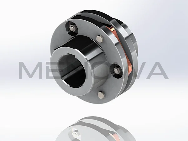
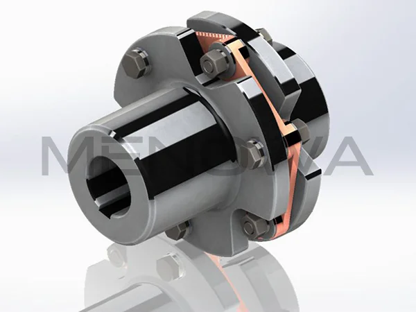
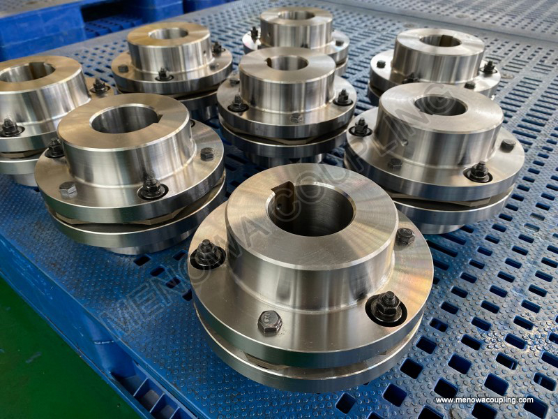
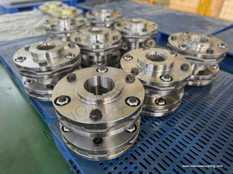
The most fundamental and widely adopted classification standard for diaphragm couplings is based on the number of diaphragm sets installed in the coupling structure, dividing the product series into single diaphragm couplings and double diaphragm couplings, two core basic types that lay the foundation for all other derivative structural designs. Single diaphragm couplings represent the original and simplest structural form of diaphragm coupling design, composed of two coupling half hubs used for shaft connection, a single set of metal diaphragms, and high-strength connecting bolts and fastening accessories. The diaphragm group in this type of coupling is usually composed of a certain number of stacked high-strength stainless steel thin sheets, processed into an integrated whole-piece structure or simple polygonal shape to meet basic torque transmission needs. In actual operation, torque is transmitted from the driving shaft hub to the metal diaphragm through the fastening bolts, and the diaphragm relies on its own elastic torsion and slight bending deformation to transfer torque to the driven shaft hub, completing the basic power transmission process. Due to the adoption of only one set of diaphragm components, the overall structure of single diaphragm couplings is extremely compact, occupying minimal axial installation space, which makes them highly suitable for mechanical equipment with limited installation dimensions and compact internal transmission layout. The assembly and disassembly process of single diaphragm couplings is relatively simple, requiring no complex positioning steps or special installation tools, and subsequent daily maintenance and component replacement work can be completed quickly, reducing equipment downtime and maintenance labor costs. In terms of transmission performance, single diaphragm couplings achieve high transmission efficiency with no rotational backlash during operation, ensuring precise synchronization of rotational speed and torque between connected shafts, which meets the basic precision requirements for conventional industrial transmission scenarios. However, the structural design of single diaphragm couplings also brings inherent performance limitations, mainly reflected in limited multi-directional misalignment compensation capacity. The single diaphragm structure can only generate small-range elastic deformation, enabling effective compensation for minor axial displacement and small-angle angular deviation between shafts, but the compensation effect for radial offset is relatively weak. Excessive radial misalignment will cause excessive stress concentration on the local area of the diaphragm, accelerating fatigue wear and shortening the service life of the diaphragm components, and may also generate obvious additional load on the equipment bearings, affecting the overall operating stability of the mechanical system. Due to these characteristics, single diaphragm couplings are mostly applied in low to medium torque transmission occasions with low shaft misalignment, stable operating load, and conventional rotational speed, such as small and medium-sized fan equipment, conventional water pump transmission systems, general mechanical processing auxiliary equipment, and ordinary industrial conveyor transmission devices, where operating conditions are stable and misalignment changes are small during long-term operation.
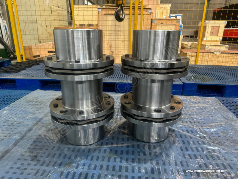
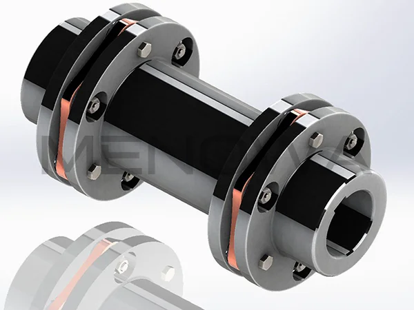
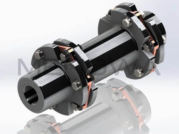
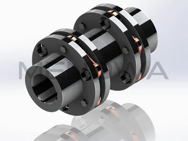
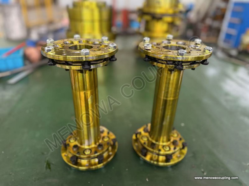
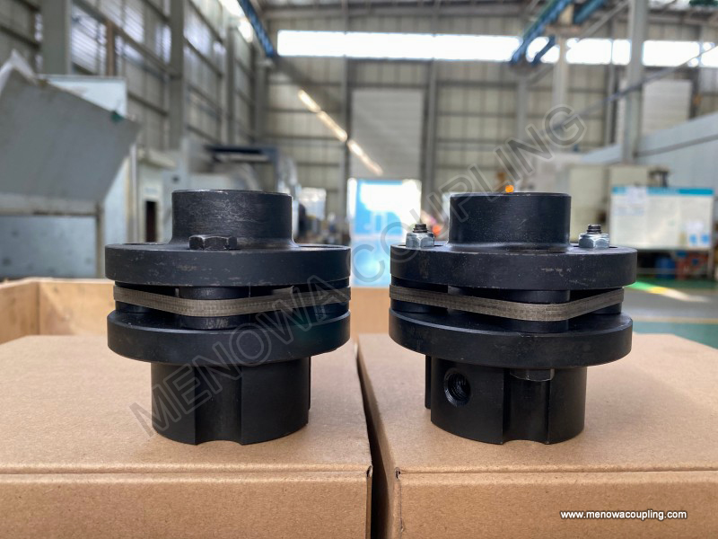
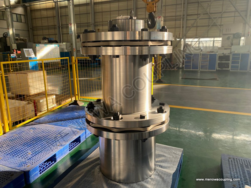
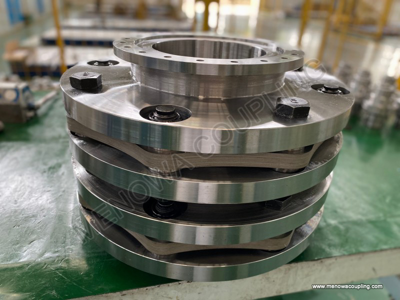
Double diaphragm couplings are optimized and upgraded on the basis of single diaphragm structural design, effectively making up for the performance shortcomings of single diaphragm types in misalignment compensation and load adaptability, and have become the mainstream type applied in medium and high-end industrial transmission fields. This type of coupling is equipped with two independent sets of metal diaphragm groups, which are symmetrically installed on both sides of the intermediate spacer sleeve, forming a three-section overall structure consisting of two coupling half hubs, two diaphragm groups, and one intermediate connecting sleeve. The intermediate spacer sleeve plays a key role in balancing the deformation of the two diaphragm sets and isolating the displacement between the driving and driven shafts, enabling the two diaphragm groups to undergo coordinated and complementary elastic deformation during equipment operation. When torque is transmitted, the driving shaft drives one diaphragm group to deform elastically, and torque is transmitted to the intermediate spacer sleeve, which then drives the other diaphragm group to synchronously deform and transfer torque to the driven shaft, realizing continuous and stable power transmission. The core advantage of double diaphragm couplings lies in their significantly enhanced multi-directional misalignment compensation capability compared with single diaphragm structures. The two sets of diaphragms can deform independently and cooperate with each other, achieving excellent compensation effects for axial displacement, angular deviation, and radial offset simultaneously, with angular displacement compensation range far exceeding that of single diaphragm couplings and traditional gear couplings. Even in mechanical systems with frequent shaft position changes, complex operating vibration, and large installation deviation, double diaphragm couplings can maintain stable transmission state without producing excessive additional reactive force on equipment bearings, effectively protecting key rotating components and extending the overall service life of mechanical equipment. In terms of torque bearing capacity, the double diaphragm matching structure can disperse transmission stress more evenly, avoiding local stress concentration of a single diaphragm under high load, thus adapting to medium and high torque transmission working conditions. In addition, double diaphragm couplings retain all the advantages of metal diaphragm transmission, including no need for lubrication, good high temperature and low temperature resistance, stable fatigue resistance, and no rotational backlash, maintaining high transmission precision during long-term high-speed operation. Although the overall axial size of double diaphragm couplings is slightly larger than that of single diaphragm types due to the addition of intermediate spacer sleeves, and the assembly process is relatively more refined, these minor drawbacks are negligible compared with their excellent comprehensive performance. Such couplings are widely used in heavy-duty industrial fields with high transmission requirements, including metallurgical rolling equipment, chemical process compressors, mining mechanical transmission systems, large-scale power plant ventilation and water supply equipment, and high-precision industrial automation production line transmission devices, as well as various mechanical systems requiring long-term continuous operation and high operational stability.
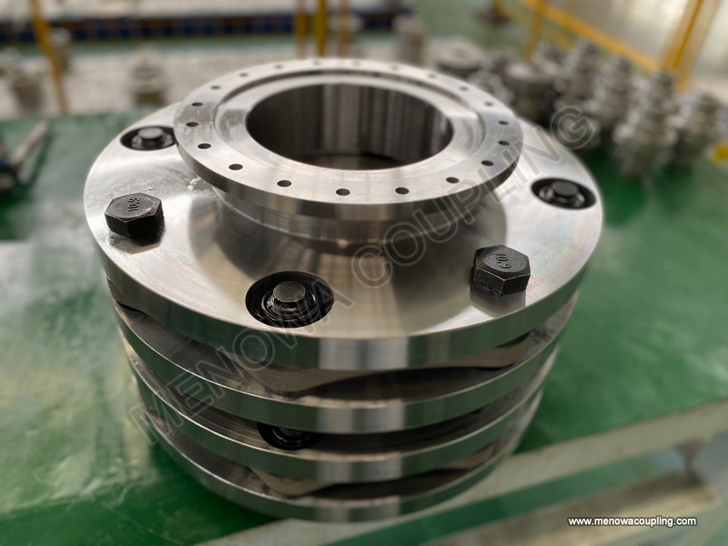
In addition to the classification by the number of diaphragm sets, diaphragm couplings can also be divided according to the structural shape and integral forming mode of the diaphragm itself, mainly including integral solid plate diaphragm couplings and multi-link segmented diaphragm couplings, two types with obvious differences in structural form and deformation flexibility. Integral solid plate diaphragm couplings adopt a single-piece integrated metal diaphragm structure, processed into circular, regular hexagonal, octagonal, or other symmetrical polygonal overall shapes through precision stamping and cutting processes, with no segmented structures or splicing gaps on the diaphragm. The overall structure of the solid plate diaphragm is firm and uniform, with good overall rigidity and strong torsional resistance, enabling stable torque transmission under impact load and fluctuating load conditions. The stress distribution on the surface of the integral diaphragm is uniform during deformation, avoiding local stress concentration caused by structural splicing, and the diaphragm has strong fatigue resistance and long service life under long-term cyclic operation. The manufacturing process of integral solid plate diaphragms is mature and standardized, with high dimensional accuracy of finished products, ensuring high concentricity after coupling installation and low vibration and noise during high-speed rotation. However, the overall rigidity of the solid plate diaphragm leads to relatively low elastic flexibility, so its deformation range and misalignment compensation capacity are limited, making it more suitable for high-speed, low misalignment, and stable load transmission scenarios. Multi-link segmented diaphragm couplings, by contrast, are composed of multiple independent strip-shaped or block-shaped diaphragm linkages arranged in a circumferential symmetrical distribution, with each diaphragm unit connected to the coupling hub and intermediate sleeve through bolts, forming a combined diaphragm whole. The segmented structural design greatly improves the elastic deformation flexibility of the diaphragm, allowing each diaphragm linkage to deform independently according to the actual misalignment condition between shafts, with larger deformation range and better adaptive compensation effect for complex and irregular shaft deviation. This type of diaphragm structure can bear larger relative displacement and offset, and has good buffering performance for slight vibration and impact during equipment operation. The disadvantage of multi-link segmented diaphragm couplings is that the overall structural rigidity is slightly lower than that of integral solid plate type, and the stress concentration at the bolt connection position of each diaphragm linkage is relatively obvious, requiring higher material fatigue resistance and processing precision. Multi-link segmented diaphragm couplings are mostly used in mechanical equipment with large installation misalignment, frequent start-stop operation, obvious operating vibration, and medium and low rotational speed working conditions, adapting to complex and changeable on-site operating environments.
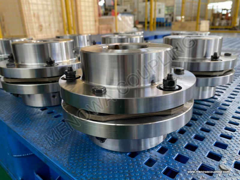
Another common classification method for diaphragm couplings is based on the shaft connection and fastening installation mode, dividing them into keyway fastening type diaphragm couplings and clamp sleeve locking type diaphragm couplings, two installation structural types designed to meet different shaft fixing and positioning requirements. Keyway fastening type diaphragm couplings adopt the traditional key and keyway matching structure to realize the connection and torque transmission between the coupling hub and the equipment shaft. The inner hole of the coupling hub is processed with standard keyways, and the shaft is equipped with matching flat keys, realizing synchronous rotation and torque transmission through the squeezing action between the key and the keyway. This connection mode has simple structure, low processing and installation cost, large torque bearing capacity, and reliable connection stability, suitable for large-torque heavy-duty transmission equipment and conventional industrial general mechanical systems. The installation and disassembly of keyway fastening type couplings are convenient and fast, and the matching degree between the key and keyway can be adjusted according to actual needs to ensure stable transmission. However, the keyway processing will cause certain structural damage to the equipment shaft and coupling hub, forming stress concentration at the keyway position, and long-term operation may cause key wear and loosening, requiring regular inspection and fastening maintenance. Clamp sleeve locking type diaphragm couplings abandon the traditional keyway connection structure and adopt the interference fit principle of elastic clamp sleeves to realize the fastening connection between the coupling hub and the shaft. Through the tightening action of fastening bolts, the clamp sleeve generates elastic shrinkage pressure, forming a tight interference fit between the hub and the shaft, realizing torque transmission through friction without any key and keyway structure. This connection mode will not cause any damage to the equipment shaft and coupling hub, with uniform stress distribution at the connection position, no stress concentration phenomenon, and high positioning accuracy and coaxiality after installation. The clamp sleeve locking structure has the advantages of convenient positioning and installation, adjustable axial position, no rotational backlash, and good shock absorption effect, making it very suitable for high-speed rotation, high-precision transmission, and frequent start-stop mechanical equipment. The main limitation of clamp sleeve locking type diaphragm couplings is that their bearing capacity for ultra-large torque is slightly lower than that of keyway fastening type, and the processing and manufacturing precision requirements of clamp sleeve components are high, leading to relatively higher overall production cost.
In practical industrial application selection, there is no single diaphragm coupling type suitable for all mechanical transmission working conditions, and the most appropriate type needs to be selected comprehensively according to equipment rotational speed, transmission torque, shaft misalignment degree, installation space, operating environment temperature, and maintenance cycle requirements. Single integral solid plate diaphragm couplings are preferred for equipment with small installation space, low misalignment, stable load, and conventional rotational speed; double multi-link segmented diaphragm couplings have obvious advantages for working conditions with large misalignment, complex vibration, medium and high torque, and long-term continuous operation; keyway fastening types are more suitable for heavy-duty low-speed transmission scenarios, while clamp sleeve locking types are more matched with high-speed high-precision transmission systems. Understanding the structural differences and performance characteristics of various types of diaphragm couplings helps to optimize the matching effect between couplings and mechanical equipment, reduce equipment operating failure rates, extend the service life of transmission components, and ensure the efficient and stable operation of the entire mechanical power transmission system in various industrial production scenarios.
Post Date: Apr 24, 2026
https://www.menowacoupling.com/china-coupling/types-of-diaphragm-coupling.html
Products

Tags
Related Articles
Flexible Diaphragm Coupling Exporter
In the global industrial transmission system, flexible diaphragm couplings have become an indispensable core component, widely used in various fields that require high-precision, high-reliability torque transmission. As a professional exporter focusing on flexible diaphragm couplings, we are committed to providing high-…Flexible Diaphragm Coupling Factory
A flexible diaphragm coupling factory is a specialized manufacturing facility dedicated to producing high-performance flexible diaphragm couplings, which are essential mechanical components used to connect two rotating shafts in various industrial applications. These couplings play a critical role in transmitting torque…Flexible Diaphragm Coupling Manufacture
Flexible diaphragm couplings stand as critical components in modern power transmission systems, bridging driving and driven shafts while accommodating misalignment, absorbing vibration, and ensuring efficient torque delivery across diverse industrial scenarios. The manufacture of these precision components integrates ma…Characteristics of Flexible Diaphragm Coupling
A flexible diaphragm coupling is a high-performance flexible coupling that uses metal elastic elements to connect two rotating shafts in industrial machinery, enabling efficient torque transmission while accommodating various types of misalignment between the shafts. Unlike many other coupling types that rely on rubber …What is Shim Pack Coupling
In the vast and interconnected field of mechanical power transmission systems, the reliable connection between rotating shafts stands as one of the most foundational and functionally critical elements for the stable operation of all types of industrial machinery and mechanical equipment. Every rotating mechanical device…Size Chart of Flexible Diaphragm Coupling
The size chart of flexible diaphragm coupling is an essential reference tool for engineers, procurement personnel, and maintenance technicians in various industrial fields, as it provides precise dimensional parameters and matching guidelines to ensure the coupling can perfectly adapt to different equipment and working …Types of Shim Pack Coupling
Shim pack couplings stand as a vital category of metal flexible transmission components widely applied in modern industrial mechanical shaft connection systems, serving the core purpose of stable torque transmission between driving and driven equipment while effectively absorbing and compensating for various minor misal…Dimensions of Flexible Diaphragm Coupling
The flexible diaphragm coupling is a high-performance metal elastic flexible coupling that plays a crucial role in connecting two rotating shafts in industrial machinery, enabling efficient torque transmission while accommodating various types of misalignment between the shafts. Unlike many other coupling types that rel…
 WeChat
 WhatsApp