Dimensions of Grid Spring Coupling
The grid spring coupling is a critical component in mechanical transmission systems, widely utilized across various industrial sectors due to its exceptional ability to accommodate misalignments, dampen vibrations, and transmit torque efficiently. While its functional advantages are well-recognized, the dimensions of a grid spring coupling play a decisive role in determining its performance, compatibility, and service life. Every dimension, from the diameter of the coupling hubs to the thickness of the grid spring, is carefully designed to meet specific operational requirements, and any deviation from the optimal dimensional parameters can lead to reduced efficiency, premature wear, or even catastrophic failure. Understanding the dimensions of grid spring couplings, their interrelationships, and the factors that influence their design is essential for engineers, maintenance personnel, and anyone involved in the selection, installation, or maintenance of mechanical transmission systems.

At the core of a grid spring coupling’s dimensional design are the components that make up its structure: the two hubs, the grid spring, the cover, and the fasteners. Each of these components has specific dimensional parameters that must be precisely defined to ensure seamless integration and optimal performance. The hubs, which connect the coupling to the driving and driven shafts, are among the most critical components in terms of dimensional accuracy. The key dimensions of the hubs include the bore diameter, the length of the bore, the outer diameter, the width of the hub flange, and the position and size of the keyway. The bore diameter is perhaps the most fundamental dimension, as it must match the diameter of the shafts it connects. A bore diameter that is too large will result in a loose fit, leading to slippage, vibration, and uneven torque transmission, while a bore that is too small will make installation impossible and may cause damage to the shafts or the coupling itself. The length of the bore is also important, as it determines the amount of contact between the hub and the shaft, which directly affects the stability of the connection. A longer bore provides a more secure fit and distributes the torque more evenly, reducing stress concentrations at the shaft-hub interface.
The outer diameter of the hub and the width of the flange are additional dimensional parameters that influence the coupling’s performance. The outer diameter affects the moment of inertia of the coupling, which in turn impacts the dynamic balance and rotational stability at high speeds. A larger outer diameter may increase the moment of inertia, leading to higher centrifugal forces and potential vibrations, while a smaller outer diameter may limit the torque-carrying capacity of the hub. The width of the flange, which is the part of the hub that interfaces with the grid spring, must be sufficient to provide adequate support for the spring while allowing for the necessary misalignment. The flange width also determines the contact area between the hub and the grid spring, which affects the distribution of forces and the overall durability of the coupling. Additionally, the keyway, which is a slot cut into the bore of the hub, has precise dimensions that must match the key on the shaft to ensure a secure connection that can transmit torque without slippage. The width, depth, and length of the keyway are all critical dimensional parameters that must be manufactured to strict tolerances to avoid play or stress concentrations.
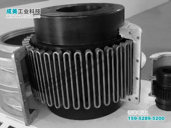
The grid spring is the heart of the grid spring coupling, and its dimensions are directly responsible for the coupling’s ability to dampen vibrations, accommodate misalignments, and transmit torque. The grid spring is typically made of a flexible, high-strength material such as spring steel, and its dimensions include the wire diameter, the pitch of the grid, the number of coils, the outer diameter of the spring, and the free length. The wire diameter is a key parameter that determines the spring’s stiffness and load-carrying capacity. A thicker wire diameter results in a stiffer spring that can transmit higher torques but may have reduced flexibility, limiting the coupling’s ability to accommodate misalignments. Conversely, a thinner wire diameter provides greater flexibility and better vibration damping but may not be able to handle high torque loads. The pitch of the grid, which is the distance between adjacent coils, affects the spring’s compressibility and flexibility. A smaller pitch results in a more compact spring with greater stiffness, while a larger pitch allows for more deformation and better misalignment accommodation.
The number of coils in the grid spring also plays a significant role in its performance. More coils increase the spring’s flexibility and vibration damping capacity, as they allow for greater deformation before reaching the elastic limit. However, an excessive number of coils can reduce the spring’s stiffness and torque-carrying capacity, leading to premature fatigue. The outer diameter of the grid spring must be compatible with the inner diameter of the coupling cover and the flange width of the hubs. If the outer diameter is too large, it may rub against the cover, causing friction and wear, while a diameter that is too small may not provide adequate contact with the hubs, reducing the torque transmission efficiency. The free length of the grid spring, which is the length of the spring when it is not under any load, is another critical dimension. The free length must be such that when the coupling is installed, the spring is slightly compressed, ensuring that it maintains constant contact with the hubs and can transmit torque effectively. If the free length is too long, the spring may not be compressed enough, leading to loose contact and slippage; if it is too short, the spring may be over-compressed, leading to premature fatigue and failure.
The cover of the grid spring coupling, which encloses the grid spring and protects it from dust, debris, and moisture, also has important dimensional parameters. The cover’s inner diameter must be slightly larger than the outer diameter of the grid spring to allow for free movement of the spring during operation, while its outer diameter is typically determined by the overall size of the coupling and the available installation space. The length of the cover must be sufficient to enclose the entire grid spring and the flanges of the hubs, providing adequate protection while allowing for the necessary axial movement due to misalignment or thermal expansion. The cover is usually secured to the hubs using fasteners such as bolts or screws, and the position and size of the fastener holes are dimensional parameters that must be precise to ensure a secure fit. The fasteners themselves also have specific dimensions, including their diameter, length, and thread size, which must be compatible with the holes in the cover and the hubs to prevent loosening during operation.
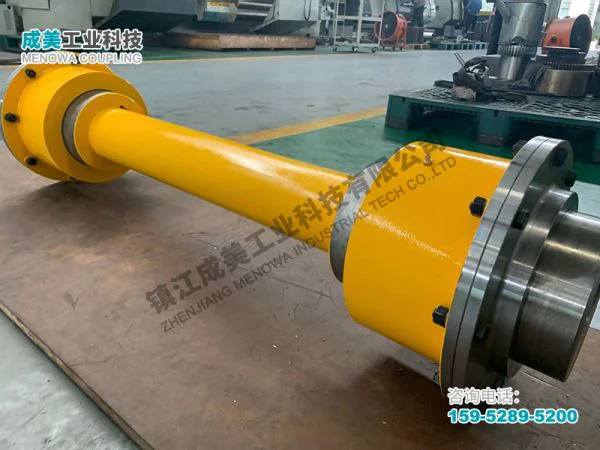
In addition to the individual component dimensions, the overall dimensions of the grid spring coupling are also critical for its compatibility with the surrounding equipment. The overall length of the coupling, which is the distance between the two ends of the hubs, must be compatible with the distance between the driving and driven shafts. If the overall length is too long, it may not fit within the available installation space, while a length that is too short may not allow for adequate misalignment accommodation. The overall diameter of the coupling, which is determined by the outer diameter of the cover, must also be considered to ensure that it does not interfere with other components in the system, such as bearings, gears, or housings. The weight of the coupling, which is a function of its dimensions and the materials used, is another important consideration, especially for high-speed applications where excessive weight can lead to increased centrifugal forces and vibrations.
The design of the dimensions of a grid spring coupling is not arbitrary; it is influenced by a variety of factors, including the torque requirements, the operating speed, the type and magnitude of misalignment, the operating environment, and the materials used. Torque transmission is one of the primary considerations, as the dimensions of the coupling must be sufficient to handle the maximum torque generated by the driving shaft without deformation or failure. The torque capacity of the coupling is directly related to the dimensions of the hubs, the grid spring, and the fasteners. For example, larger hubs with a greater cross-sectional area can transmit higher torques, while a thicker grid spring wire diameter increases the spring’s load-carrying capacity. The operating speed also affects the dimensional design, as higher speeds require more precise dimensional tolerances to ensure dynamic balance and reduce vibrations. At high speeds, even small dimensional deviations can lead to significant centrifugal forces, which can cause the coupling to vibrate, wear prematurely, or fail.
Misalignment accommodation is another key factor that influences the dimensional design of grid spring couplings. Misalignments can be axial, radial, or angular, and the coupling’s dimensions must be designed to accommodate these misalignments without causing excessive stress or wear. Axial misalignment, which is the displacement of the shafts along their axial axis, is accommodated by the flexibility of the grid spring and the length of the hubs. The grid spring can compress or extend to absorb axial movement, while the length of the hubs ensures that the connection remains secure even when the shafts are displaced. Radial misalignment, which is the lateral displacement of the shafts, is accommodated by the flexibility of the grid spring and the clearance between the grid spring and the cover. The grid spring can bend to compensate for radial displacement, while the clearance ensures that the spring does not rub against the cover. Angular misalignment, which is the tilt of one shaft relative to the other, is accommodated by the flexibility of the grid spring and the design of the hub flanges. The grid spring can twist to compensate for angular misalignment, while the hub flanges are designed to maintain contact with the spring even when the shafts are tilted.
The operating environment also plays a role in the dimensional design of grid spring couplings. In harsh environments, such as those with high temperatures, corrosive substances, or excessive dust and debris, the dimensions may need to be adjusted to ensure durability. For example, in high-temperature environments, the materials used may expand, so the dimensions must be designed to accommodate thermal expansion without causing binding or excessive stress. In corrosive environments, the coupling may need to be larger to accommodate protective coatings or materials that resist corrosion, while the clearance between components may need to be increased to prevent the buildup of corrosive substances. The materials used in the coupling also influence its dimensions, as different materials have different strength, flexibility, and density properties. For example, a coupling made of a high-strength alloy may have smaller dimensions than one made of a lower-strength material, as it can transmit the same torque with a smaller cross-sectional area.
Dimensional tolerances are another critical aspect of grid spring coupling design. Tolerances are the allowable deviations from the nominal dimensions, and they ensure that the coupling components fit together properly and perform as intended. Tight tolerances are required for critical dimensions such as the bore diameter, keyway dimensions, and grid spring wire diameter, as even small deviations can affect the coupling’s performance. For example, a bore diameter with a tolerance that is too loose can result in a loose fit between the hub and the shaft, leading to slippage and vibration, while a tolerance that is too tight can make installation difficult and cause damage to the components. The tolerances are typically specified based on the application requirements, with higher precision required for high-speed, high-torque applications.
The selection of the correct dimensions for a grid spring coupling is a critical step in ensuring the reliability and efficiency of a mechanical transmission system. Engineers must carefully consider the torque requirements, operating speed, misalignment levels, and operating environment when selecting the dimensions of the coupling. In many cases, standard grid spring couplings are available with predefined dimensions that meet the needs of most applications. However, in some cases, custom dimensions may be required to meet specific application requirements. Custom dimensions may involve adjusting the bore diameter, hub length, grid spring dimensions, or overall length of the coupling to fit unique shaft sizes, installation spaces, or torque requirements. When designing custom dimensions, it is essential to ensure that all components are compatible and that the coupling can still accommodate misalignments, dampen vibrations, and transmit torque effectively.
Installation and maintenance of grid spring couplings also require careful attention to their dimensions. During installation, the shafts must be aligned as accurately as possible to minimize the amount of misalignment that the coupling must accommodate. The bore of the hubs must be properly sized to fit the shafts, and the keyway must be aligned correctly to ensure a secure connection. The grid spring must be installed correctly, with the proper amount of compression to ensure constant contact with the hubs. During maintenance, the dimensions of the coupling components should be inspected regularly to check for wear, deformation, or dimensional changes. For example, wear on the grid spring can reduce its thickness and flexibility, while wear on the hub flanges can change their width and affect the contact with the spring. Any dimensional changes beyond the allowable tolerances can indicate that the coupling needs to be repaired or replaced.
The performance of a grid spring coupling is directly related to its dimensions, and any compromise in dimensional accuracy can lead to a range of issues, including reduced torque transmission efficiency, increased vibration, premature wear, and failure. For example, if the grid spring wire diameter is too thin, it may fatigue and break under high torque loads, leading to a loss of power transmission. If the bore diameter of the hub is too large, the hub may slip on the shaft, causing damage to both the shaft and the hub. If the overall length of the coupling is too short, it may not be able to accommodate the required misalignment, leading to excessive stress on the coupling components and the shafts. Therefore, it is essential to ensure that the dimensions of the grid spring coupling are designed, manufactured, and maintained to the highest standards of accuracy.
In conclusion, the dimensions of a grid spring coupling are a critical factor in its performance, compatibility, and service life. Every component, from the hubs to the grid spring to the cover, has specific dimensional parameters that must be carefully designed and manufactured to meet the requirements of the application. The bore diameter, hub length, grid spring wire diameter, pitch, and overall length are just a few of the key dimensions that influence the coupling’s ability to transmit torque, accommodate misalignments, and dampen vibrations. The design of these dimensions is influenced by factors such as torque requirements, operating speed, misalignment levels, operating environment, and materials used. By understanding the importance of these dimensions and ensuring that they are correctly selected, installed, and maintained, engineers can ensure that grid spring couplings perform reliably and efficiently in a wide range of industrial applications. Whether using standard or custom dimensions, the goal is to create a coupling that is perfectly suited to the needs of the transmission system, providing long-lasting, trouble-free performance.
Post Date: May 6, 2026
https://www.menowacoupling.com/china-coupling/dimensions-of-grid-spring-coupling.html

Supply
Related Articles
Diagram of Grid Spring Coupling
A grid spring coupling is a versatile mechanical device designed to transmit torque between two rotating shafts while accommodating misalignments, absorbing shock loads, and reducing vibration in various industrial applications. Its unique structural design, which combines rigidity with flexibility, makes it an indispen…Grid Spring Coupling Manufacture
Grid spring couplings are essential mechanical components widely used in industrial power transmission systems, serving as the critical connection between driving and driven shafts to transmit torque while accommodating misalignments and absorbing shocks. The manufacture of grid spring couplings requires precise enginee…Gap Chart of Grid Spring Coupling
The gap chart of grid spring coupling is an indispensable technical document in the field of mechanical transmission, serving as a core guide for the installation, operation, maintenance, and fault diagnosis of grid spring couplings. Grid spring couplings, as a type of metallic flexible coupling widely used in medium to…Grid Spring Coupling Supplier
In the complex and interconnected world of industrial machinery, the role of coupling components cannot be overstated. These critical parts serve as the bridge between rotating shafts, ensuring the smooth and efficient transmission of power while accommodating misalignments and reducing operational stress. Among the var…Structure of Grid Spring Coupling
The grid spring coupling is a crucial component in industrial power transmission systems, designed to connect two rotating shafts while accommodating misalignments, absorbing vibrations, and protecting machinery from shock loads. Its unique structure combines the rigidity needed for efficient torque transmission with th…Characteristics of Grid Spring Coupling
A grid spring coupling is a specialized mechanical component designed to transmit torque between two rotating shafts while accommodating various forms of misalignment and mitigating the effects of vibration and shock loads. Unlike rigid couplings that require precise alignment and offer no flexibility, grid spring coupl…Components of Grid Spring Coupling
A grid spring coupling is a sophisticated mechanical device designed to transmit torque between two rotating shafts while accommodating misalignments, absorbing vibrations, and cushioning shock loads. Its robust yet flexible structure makes it indispensable in a wide range of industrial applications, from heavy machiner…
 WeChat
 WhatsApp