Gap Chart of Grid Spring Coupling
The gap chart of grid spring coupling is an indispensable technical document in the field of mechanical transmission, serving as a core guide for the installation, operation, maintenance, and fault diagnosis of grid spring couplings. Grid spring couplings, as a type of metallic flexible coupling widely used in medium to heavy-duty applications, rely on their grid-shaped spring elements to transmit torque, compensate for shaft misalignment, and absorb shock loads, thereby protecting the drive system and connected equipment from damage. The gap chart, which systematically records and presents the gap parameters of key components of the coupling, provides accurate data support for ensuring the stable and efficient operation of the coupling, and plays a decisive role in extending the service life of the entire transmission system. In practical engineering applications, the rational use of the gap chart can not only avoid potential failures caused by improper gap settings but also optimize the performance of the coupling, making it adapt to different working conditions and load requirements.

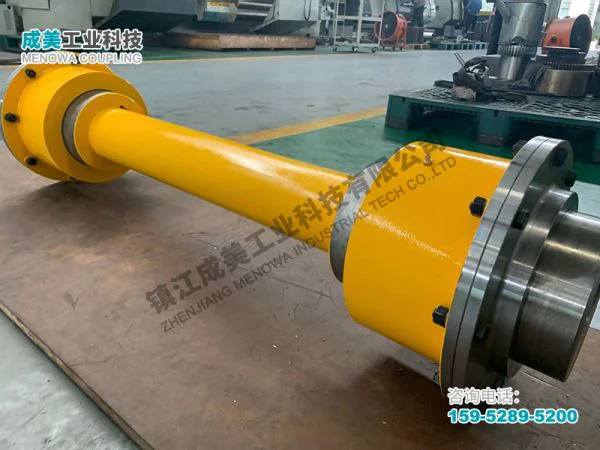
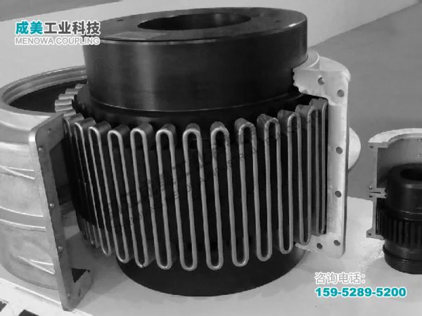
To fully understand the gap chart of grid spring coupling, it is first necessary to clarify the basic structure and working principle of the grid spring coupling itself. A typical grid spring coupling consists of two hubs, a grid spring element, seals, and a housing. The hubs are usually made of high-strength alloy steel, with evenly distributed teeth on their inner or outer surfaces, which mesh with the grid spring element. The grid spring, the core component of the coupling, is made of high-tensile alloy steel through precision processing, with a unique curved or looped structure that enables it to deform within a certain range. When the coupling is in operation, the grid spring transmits torque between the two hubs through the meshing with the hub teeth, and at the same time, relies on its own flexibility to compensate for the relative misalignment between the two shafts, including radial misalignment, angular misalignment, and axial misalignment. In addition, the grid spring can also absorb shock and vibration generated during the operation of the equipment, reducing the impact of peak loads on the drive system and connected components. The seals and housing are used to protect the internal components from dust, moisture, and other contaminants, and to ensure the effective lubrication of the meshing surfaces between the grid spring and the hubs, which is crucial for reducing wear and extending the service life of the coupling.
The gap chart of grid spring coupling is essentially a data table or graph that records the standard gap values, allowable deviation ranges, and measurement methods of each key gap in the coupling under different working conditions and specifications. The gaps involved in the gap chart mainly include the radial gap between the grid spring and the hub teeth, the axial gap between the two hubs, the end gap between the grid spring and the housing, and the radial and axial gaps between the seals and other components. Each of these gaps has a specific functional significance and directly affects the performance and service life of the coupling. For example, the radial gap between the grid spring and the hub teeth is used to compensate for the radial misalignment between the two shafts and to ensure that the grid spring can freely deform during torque transmission without being stuck or overloaded. The axial gap between the two hubs is designed to accommodate the axial expansion and contraction of the shafts caused by temperature changes during operation, preventing the coupling from being subjected to axial forces that may lead to component damage. The end gap between the grid spring and the housing ensures that the grid spring has sufficient space for movement during operation, avoiding friction and wear between the grid spring and the housing.
The formulation of the gap chart is based on a large number of experimental data, theoretical calculations, and practical application experience. During the design and manufacturing process of grid spring couplings, manufacturers need to consider various factors that may affect the gap parameters, including the material properties of the components, the structural design of the coupling, the rated torque, the operating speed, the working temperature range, and the expected service life. For example, the material of the grid spring directly affects its elastic modulus and fatigue strength, which in turn determines the reasonable range of the radial gap between the grid spring and the hub teeth. Couplings used in high-temperature environments need to have a larger axial gap to accommodate the greater axial expansion of the shafts, while couplings operating at high speeds require more precise gap control to avoid resonance and vibration. Through repeated tests and verifications, manufacturers determine the standard gap values and allowable deviation ranges for each specification of grid spring coupling, and compile these data into a gap chart to provide a reliable reference for the installation and maintenance of the coupling.
The measurement of the gaps recorded in the gap chart is a key link in the installation and maintenance of grid spring couplings, and the accuracy of the measurement directly affects the effectiveness of the gap chart. There are various methods for measuring the gaps of grid spring couplings, including the feeler gauge method, the dial indicator method, and the laser alignment method, each of which has its own characteristics and scope of application. The feeler gauge method is the most commonly used method due to its simplicity, convenience, and low cost. It uses feeler gauges of different thicknesses to measure the gap between components, which is suitable for measuring the radial gap between the grid spring and the hub teeth, and the end gap between the grid spring and the housing. When using the feeler gauge method, it is necessary to ensure that the feeler gauge is inserted smoothly into the gap without applying excessive force, so as to avoid damaging the components or causing measurement errors. The dial indicator method is more accurate than the feeler gauge method and is suitable for measuring the axial gap between the two hubs and the radial runout of the hubs. When using this method, the dial indicator is fixed on a stable support, and the measuring head is in contact with the surface of the component to be measured. By rotating the coupling, the maximum and minimum values of the gap can be read, and the actual gap value can be calculated. The laser alignment method is a high-precision measurement method, suitable for large-scale, high-precision grid spring couplings used in key equipment. It uses laser beams to measure the misalignment and gap between the two shafts, with high measurement accuracy and strong anti-interference ability, but the equipment cost is relatively high.
The correct interpretation of the gap chart is crucial for the rational use of grid spring couplings. When checking the coupling, the measured gap values should be compared with the standard values in the gap chart. If the measured values are within the allowable deviation range, it indicates that the coupling is in a normal working state; if the measured values exceed the allowable deviation range, it is necessary to analyze the causes and take corresponding measures in a timely manner. For example, if the radial gap between the grid spring and the hub teeth is too small, it may be due to the wear of the hub teeth or the deformation of the grid spring, which will lead to increased friction between the components, increased energy consumption, and even jamming of the coupling. In this case, the worn or deformed components should be replaced in time to restore the gap to the standard range. If the axial gap between the two hubs is too large, it may be due to the loosening of the hub installation or the excessive axial expansion of the shafts, which will affect the torque transmission efficiency and may cause vibration of the coupling. At this time, the hubs should be repositioned and fixed, or the gap should be adjusted according to the working temperature to ensure that it meets the requirements of the gap chart.
The gap chart of grid spring coupling also plays an important role in fault diagnosis and maintenance. In the daily operation of the coupling, regular measurement and recording of the gap parameters, and comparison with the gap chart can help detect potential faults in advance. For example, if the radial gap between the grid spring and the hub teeth increases rapidly during operation, it may indicate that the grid spring is fatigue damaged or the hub teeth are severely worn, and the components need to be inspected and replaced in time to avoid sudden failure of the coupling. In addition, the gap chart can also provide a reference for the maintenance cycle and maintenance content of the coupling. According to the gap changes recorded in the gap chart, the maintenance plan can be formulated reasonably, such as lubricating the coupling regularly, checking the wear of components, and adjusting the gap, so as to extend the service life of the coupling and reduce maintenance costs.
It should be noted that the gap chart of grid spring coupling is not a fixed document, and its standard gap values and allowable deviation ranges may vary according to the specific type and specification of the coupling. Therefore, when using the gap chart, it is necessary to select the corresponding gap chart according to the model and specification of the coupling to ensure the accuracy of the reference data. In addition, the working environment of the coupling also has a certain impact on the gap parameters. For example, in harsh environments such as high temperature, high humidity, and heavy dust, the wear speed of the components will be accelerated, and the gap will change more quickly. Therefore, in such environments, the frequency of gap measurement should be increased, and the maintenance measures should be adjusted according to the actual gap changes to ensure the stable operation of the coupling.
In practical engineering applications, the gap chart of grid spring coupling is widely used in various fields, including metallurgy, mining, petroleum, chemical industry, power generation, and transportation. In the metallurgical industry, grid spring couplings are used to connect motors and rolling mills, and the gap chart is used to ensure the accurate alignment of the shafts and the stable transmission of torque, which is crucial for improving the production efficiency and product quality of rolling mills. In the mining industry, the working environment is harsh, and the coupling is subjected to large shock loads and misalignment. The gap chart helps to timely detect the wear and damage of the coupling components, avoid equipment downtime caused by coupling failure, and ensure the normal operation of mining equipment. In the power generation industry, grid spring couplings are used in power units such as steam turbines and generators. The precise control of the gap parameters is essential for the safe and stable operation of the power units, and the gap chart provides a reliable guarantee for this.
With the continuous development of mechanical transmission technology, the performance requirements of grid spring couplings are getting higher and higher, and the gap chart, as an important technical document, is also constantly optimized and improved. Modern manufacturing technologies, such as computer-aided design (CAD) and finite element analysis (FEA), are widely used in the design and development of grid spring couplings, which can more accurately calculate the gap parameters and optimize the structural design of the coupling. At the same time, the application of intelligent measurement equipment makes the measurement of gap parameters more efficient and accurate, providing more reliable data support for the formulation and update of the gap chart. In addition, with the popularization of predictive maintenance technology, the gap chart is combined with real-time monitoring data of the coupling, which can realize the predictive diagnosis of coupling faults, further improving the reliability and service life of the transmission system.
In conclusion, the gap chart of grid spring coupling is a key technical document that runs through the entire life cycle of the coupling, from design, manufacturing, installation, operation to maintenance. It provides accurate data support for the rational use and maintenance of the coupling, and plays an irreplaceable role in ensuring the stable, efficient, and safe operation of the mechanical transmission system. For engineering and technical personnel engaged in mechanical transmission, mastering the use method and interpretation skills of the gap chart is essential. Only by correctly using the gap chart, regularly measuring and adjusting the gap parameters of the coupling, can we give full play to the performance advantages of the grid spring coupling, reduce the occurrence of faults, and extend the service life of the equipment, thus bringing greater economic benefits to the enterprise. In the future, with the continuous progress of technology, the gap chart will be more intelligent and precise, making greater contributions to the development of the mechanical transmission industry.
Post Date: May 6, 2026
https://www.menowacoupling.com/china-coupling/gap-chart-of-grid-spring-coupling.html

Supply
Related Articles
Structure of Grid Spring Coupling
The grid spring coupling is a crucial component in industrial power transmission systems, designed to connect two rotating shafts while accommodating misalignments, absorbing vibrations, and protecting machinery from shock loads. Its unique structure combines the rigidity needed for efficient torque transmission with th…Characteristics of Grid Spring Coupling
A grid spring coupling is a specialized mechanical component designed to transmit torque between two rotating shafts while accommodating various forms of misalignment and mitigating the effects of vibration and shock loads. Unlike rigid couplings that require precise alignment and offer no flexibility, grid spring coupl…Components of Grid Spring Coupling
A grid spring coupling is a sophisticated mechanical device designed to transmit torque between two rotating shafts while accommodating misalignments, absorbing vibrations, and cushioning shock loads. Its robust yet flexible structure makes it indispensable in a wide range of industrial applications, from heavy machiner…Diagram of Grid Spring Coupling
A grid spring coupling is a versatile mechanical device designed to transmit torque between two rotating shafts while accommodating misalignments, absorbing shock loads, and reducing vibration in various industrial applications. Its unique structural design, which combines rigidity with flexibility, makes it an indispen…Grid Spring Coupling Manufacture
Grid spring couplings are essential mechanical components widely used in industrial power transmission systems, serving as the critical connection between driving and driven shafts to transmit torque while accommodating misalignments and absorbing shocks. The manufacture of grid spring couplings requires precise enginee…Dimensions of Grid Spring Coupling
The grid spring coupling is a critical component in mechanical transmission systems, widely utilized across various industrial sectors due to its exceptional ability to accommodate misalignments, dampen vibrations, and transmit torque efficiently. While its functional advantages are well-recognized, the dimensions of a …Grid Spring Coupling Supplier
In the complex and interconnected world of industrial machinery, the role of coupling components cannot be overstated. These critical parts serve as the bridge between rotating shafts, ensuring the smooth and efficient transmission of power while accommodating misalignments and reducing operational stress. Among the var…
 WeChat
 WhatsApp